1. Introduction
A modern tubular steel tower is transported in sections and assembled on site. Each section ends in a forged or rolled ring flange welded to the shell, and neighbouring flanges are clamped together by a circle of large preloaded bolts, usually on the inside of the tower so that they can be reached from the internal platforms. The joint is designed to requirements set out in the international standard for towers and foundations (IEC, 2020) and in certification documents such as the standard of DNV GL (2016). It carries the bending moment from rotor thrust as tension in the bolts on the windward side and as compression through the flange contact on the other, and the wind reverses and varies that loading many millions of times.
Because the bolts are preloaded, only a small part of each load fluctuation reaches them as long as the flanges stay in contact. This shielding is what makes the joint fatigue resistant, and it is also why the joint is unforgiving. Anything that reduces preload or disturbs the contact, whether a gap between flanges, settlement of surface coatings, inadequate tightening or self-loosening, raises the stress range in the bolt far out of proportion to the change itself. Bolt fractures found at inspection, or a flange separation, are therefore the visible end of a chain that may have begun at fabrication, at installation or during operation.
Investigations of such events tend to be organised around whoever is asking: the operator, the manufacturer, the insurer. This article proposes a protocol that is independent of the commissioning party and that orders the work so that perishable evidence is captured first and each later stage tests explicit hypotheses. It does not describe any actual failure. The protocol is offered as a methodological proposal, to be refined by those who apply it.
2. How Ring-Flange Joints Carry Load and Fail
A sound investigation needs a model of normal behaviour against which the evidence can be read. Two parts of the literature supply it: the mechanics of the preloaded L-flange, and the catalogue of ways in which preload and bolt integrity are lost.
2.1. Mechanics of the preloaded L-flange
Design practice idealises the ring as a series of identical segments, each an L-shaped flange with one bolt, loaded by the shell force of that segment. Because the shell wall is offset from the bolt axis, the segment is loaded eccentrically and the relation between shell force and bolt force is nonlinear: nearly flat while the clamped contact persists, then steepening as the flange opens on the shell side. The plastic limit models set out by Petersen (1988) are used for ultimate strength, and the trilinear bolt load function of Schmidt and Neuper (1997) is widely used for fatigue. Seidel (2001) examined these models in detail. The general treatment of preloaded joints, including load factor, tightening scatter and embedding losses, follows the guideline VDI (2015) and texts such as Bickford (2008). The fatigue verification itself uses the detail categories and damage summation of Eurocode 3 (CEN, 2005b).
2.2. Recognised causes of failure
The bolt load function assumes flat flanges in full contact. Real flanges have flatness deviations and taper from welding and machining, and Schaumann and Seidel (2000) showed by analysis that gaps between the flanges before tightening can raise bolt fatigue loads considerably, depending on the form and extent of the gap. Tolerances on flatness are accordingly specified in the tower standard (IEC, 2020). Preload itself is uncertain: it depends on the tightening method, on lubrication and on the procedures of the execution standard (CEN, 2018), and it falls over time through embedding and relaxation. Tightening is carried out in several passes with hydraulic torque or tensioning tools, the scatter of the achieved preload differs between methods, and the tightening factor of the VDI guideline exists to cover it. A check of preload after an initial period of operation is commonly specified for the same reason. Under transverse slip a bolt can rotate loose, the mechanism identified by Junker (1969). High-strength bolts of property class 10.9 are in addition susceptible to hydrogen-assisted cracking if hardness is excessive or if hydrogen is introduced by coating processes or corrosion, and to corrosion fatigue where the protective coating has failed (ASM International, 2002).
3. The Proposed Protocol
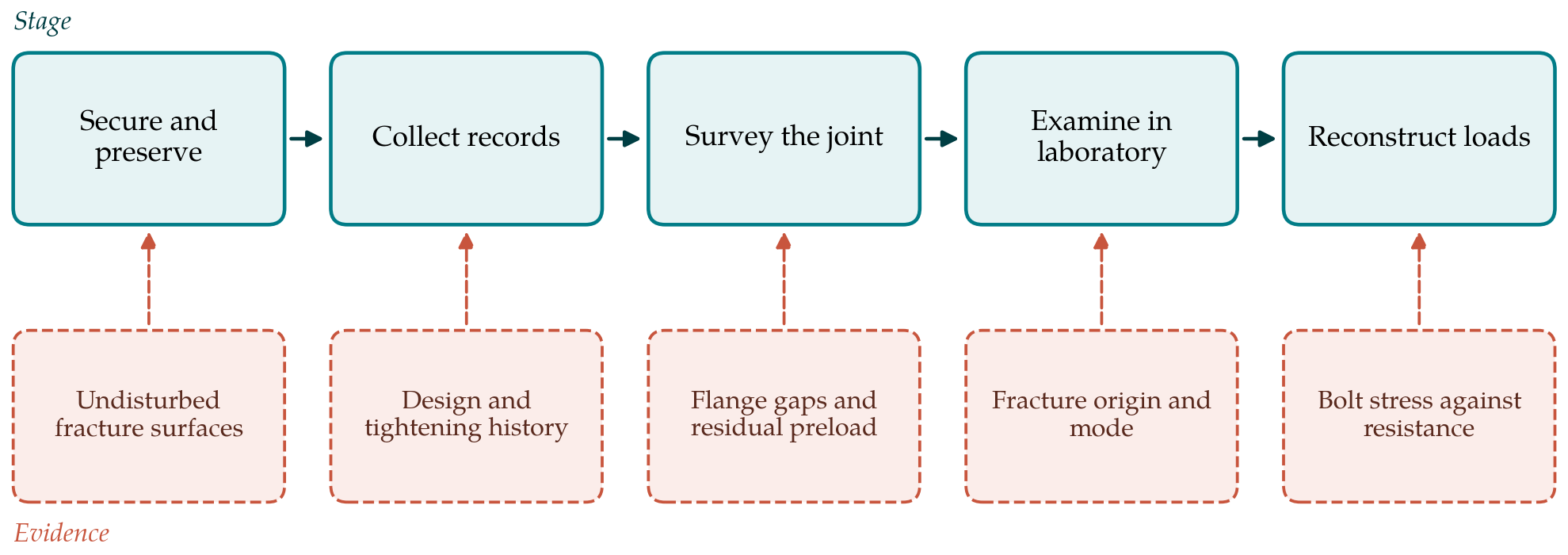
The protocol has six stages. Table 1 sets out the activities and records of each, and Figure 1 pairs the first five stages with the evidence each is meant to secure; the sixth stage draws that evidence together. The order reflects how quickly evidence degrades: fracture surfaces corrode within days in a damp tower, whereas design documents do not change.
| Stage | Principal activities | Record produced |
|---|---|---|
| 1. Secure and preserve | Make safe, photograph, number bolt positions, protect fracture surfaces | Photo log, bolt map, custody forms |
| 2. Collect records | Gather design, fabrication, installation, maintenance and operating data | Document register and timeline |
| 3. Survey the joint | Measure gaps, flatness, residual preload and coating condition | Survey sheets by bolt position |
| 4. Laboratory examination | Fractography, metallography, hardness, chemistry and tensile tests | Laboratory report per sample |
| 5. Reconstruct loads | Derive section loads, bolt forces and fatigue damage for candidate conditions | Calculation file with assumptions |
| 6. Weigh hypotheses | Test each candidate cause against all the evidence and report | Hypothesis matrix and final report |
3.1. Stage 1: Secure the site and preserve evidence
The first duty is safety: a joint with broken bolts has reduced capacity, and the turbine is stopped and the structure assessed before anyone works at the flange. Once access is safe, the joint is photographed in its found state, all the way round, before anything is moved. Every bolt position is numbered from a fixed datum such as the door axis, and the numbering is marked on the flange. Broken bolts, nuts and washers are collected with their positions recorded. Fracture surfaces are kept from touching each other, dried, and protected in desiccant packaging; they are not cleaned or fitted back together. A custody record follows each item from this point.
3.2. Stage 2: Collect the records
Records are requested in parallel, from all parties, against a fixed list. Design records include the load assumptions under the applicable edition of the turbine design standard (IEC, 2019), the flange and bolt calculations and the specified preload and tolerances. Fabrication records include flange material certificates, flatness measurements after welding, and coating reports. For the bolts, the inspection certificates to the product standards for preloaded assemblies and for fastener properties are obtained, with lot numbers (CEN, 2015; ISO, 2013). Installation and maintenance records should show the tightening method, tool calibration, lubricant, sequence and any retightening or bolt replacement. Operating data from the turbine controller, covering power, rotor speed, nacelle direction, tower acceleration, alarms and stops, are secured for the whole period available. The items are entered in a single timeline.
3.3. Stage 3: Survey the joint in the field
The survey establishes the condition of the parts that did not fail, which is often more informative than the fracture. Flange gaps are measured with feeler gauges at every bolt position, inside and, where accessible, outside. Residual preload in intact bolts is estimated by one consistent method, such as ultrasonic elongation measurement where reference lengths exist or controlled hydraulic lift-off, and the uncertainty of the method is stated. Any bolt that can be turned by hand is noted. The condition of coatings, signs of water ingress, fretting products at the flange interface and marks of relative movement are photographed. When the joint is opened, flange flatness and taper are measured, and the contact pattern on the mating faces is recorded before cleaning. All readings are tabulated against bolt number so that they can be compared with the positions of the fractures.
3.4. Stage 4: Examine bolts and flange material in the laboratory
Laboratory work proceeds from non-destructive to destructive. Each fracture surface is documented under low magnification before cleaning and is then examined by scanning electron microscopy. The features to be distinguished are well described in the failure analysis literature (ASM International, 2002). Fatigue shows beach marks, a smooth propagation zone and a final overload area, with origins usually at the first engaged thread or the head fillet; hydrogen-assisted cracking shows intergranular facets near the origin; overload shows dimples throughout. The relative size of the fatigue and overload zones indicates how highly the bolt was stressed when it finally broke. Sections are then taken for microstructure, decarburisation and thread-root form, hardness traverses are made, and chemical composition and tensile properties are checked against the property class (ISO, 2013). Unbroken bolts from the same joint and lot are examined for cracks, since they reveal how far damage had spread.
3.5. Stage 5: Reconstruct loads and bolt stresses
The analysis stage asks whether the joint as designed, and the joint as found, would be expected to survive the loads it saw. Section loads at the flange are derived from the design load cases and, where operating data allow, from the recorded history. Bolt forces are computed with the segment model for the nominal condition and then with a finite element model of the flange ring that includes the measured gaps and the estimated preload distribution. Stress ranges are counted by the rainflow method (ASTM International, 2017) and summed by linear damage accumulation (Miner, 1945) against the detail category for the bolt. The calculation is repeated for each candidate condition: nominal, reduced preload, measured gap, and combinations of these. Static resistance of the joint at the ultimate limit state is checked with the rules for preloaded bolts in tension (CEN, 2005a).
3.6. Stage 6: Weigh the hypotheses and report
Candidate causes are written down at the start and kept open until the evidence closes them. A matrix lists each hypothesis against each item of evidence, marked as supporting, contradicting or neutral. A hypothesis survives only if nothing contradicts it and if it explains the position of the first fractures around the circumference, their fracture mode and their timing. The report separates observations from inferences, states the uncertainty of each measurement, and distinguishes the initiating cause from contributing conditions and from consequential damage. Where the evidence cannot discriminate between two causes, the report says so.
4. Applying the Protocol in Practice
Three practical matters affect how the protocol is used. Access and time are limited: a stopped turbine costs its operator revenue, and stages 1 and 3 have to be planned so that one or two visits suffice. Several parties will have an interest in the outcome and may be in dispute, so joint attendance at the survey and at destructive tests, with agreed test plans, protects the standing of the results. And the same tower design usually exists at other sites. Findings that point to a systematic cause, such as a flange tolerance or a tightening procedure, call for a screening inspection of sister joints, for which the survey sheets of stage 3 can serve as a template.
5. Limitations and What Remains to Be Shown
The protocol is proposed and has not been validated in this article by application to a failure. Its stages follow general failure analysis practice and the documented mechanics of the joint, but whether the order and the records specified are sufficient in real investigations can only be judged by use. A retrospective trial, in which completed investigations are compared against the protocol to see what evidence it would have added or missed, would be a first test.
Certain limitations can be foreseen. Residual preload measured after a failure is not the preload before it, because load redistributes as bolts break. Operating records seldom contain direct measurements of tower loads, so reconstructed load histories carry large uncertainty, and the fatigue damage sum is sensitive to it. The segment model, and even ring models with measured gaps, simplify contact and friction. Finally, the protocol addresses flange connections with through-bolts in tubular steel towers; foundation anchor cages, friction connections and hybrid towers involve different mechanics and would need their own versions.
6. Conclusion
The bolted ring-flange joint of a wind turbine tower depends on preload and flange contact for its fatigue resistance, and failures usually involve several interacting deficiencies. The six-stage protocol proposed here orders an investigation so that perishable evidence is captured first, the unfailed parts of the joint are surveyed as carefully as the fractures, laboratory findings and load reconstruction are tied to bolt position, and conclusions are reached by explicit elimination of hypotheses. It is put forward for trial and criticism by investigators, operators and certifiers, whose experience will decide which of its provisions deserve to become routine.
Conflict of interest
To be declared by the author(s) before publication.
Funding
To be declared by the author(s) before publication.