1. Introduction
A large part of the short-span road bridge stock in many countries dates from the decades after the Second World War. The decks of these bridges are typically solid or beam-and-slab reinforced concrete, designed for axle loads lower than those now permitted and built before the link between cover, concrete quality and reinforcement corrosion was written into codes. In a coastal climate the consequences are familiar: chloride from spray and salt-laden wind has reached the reinforcement, the soffit shows rust staining, cracking along the bars and delamination, and an assessment finds a shortfall in flexural or shear capacity that corrosion can only enlarge (Broomfield, 2007).
Owners faced with such a deck need two things from an intervention: the deterioration must be arrested, and capacity must be restored or raised. Externally bonded fibre-reinforced polymer has been the usual lightweight means of adding capacity, but its epoxy adhesive is intolerant of damp substrates and low application temperatures, forms a vapour barrier over concrete that may still hold chloride, and softens at moderate temperature. Textile-reinforced mortar, known in North American guidance as fabric-reinforced cementitious matrix, replaces the resin with an inorganic mortar and was developed largely to avoid these drawbacks (Triantafillou and Papanicolaou, 2006; Koutas et al., 2019).
This article proposes a procedure for planning such a retrofit. It is written as a method, in sequence, and reports no project. The steps are drawn from design guidance for the material, from the European standards for concrete repair, and from the research literature, and where these sources leave a question unanswered the article says so.
2. Background
Two bodies of knowledge have to be combined: how textile-reinforced mortar carries load, and how a chloride-contaminated deck should be repaired.
2.1. The strengthening material
The system consists of one or more layers of open mesh textile, made of carbon, alkali-resistant glass, basalt or polyparaphenylene benzobisoxazole fibre rovings, embedded in a few millimetres of fine mortar (Brameshuber, 2006). Because the mortar does not fully impregnate the rovings, the inner filaments can slip relative to the outer ones, and failure may occur by debonding from the substrate, by slip of the textile within the matrix or by rupture of the fibres (D'Ambrisi and Focacci, 2011). In direct tension the composite shows an uncracked stage, a stage of multiple cracking and a final stage governed by the textile, and the standard coupon test is designed to capture all three (RILEM TC 232-TDT, 2016). Tests on slabs and beams have shown useful gains in flexural capacity, generally somewhat lower than with polymer systems of equal fibre area (Schladitz et al., 2012; Loreto et al., 2014; Raoof et al., 2017).
Design guidance exists in the United States and Italy. The American Concrete Institute guide bases design on tensile properties measured on the cracked composite, limits the strain that may be assumed in the textile, and caps the increase in capacity that may be credited to the system (ACI Committee 549, 2013). The Italian guideline takes a comparable approach using bond tests on the intended substrate (CNR, 2018).
2.2. Repair of a chloride-contaminated deck
The European standard EN 1504-9 arranges the options for repair under principles, among them restoring the concrete, strengthening, restoring passivity of the reinforcement and cathodic protection (CEN, 2008). Its logic is that the cause of deterioration is diagnosed first and the principle chosen to suit. For chloride-induced corrosion the well-known hazard of local patching is the incipient anode: steel in the fresh repair becomes cathodic to steel in the adjoining contaminated concrete, and corrosion restarts at the edge of the patch (Bertolini et al., 2013). A strengthening layer bonded over concrete that still contains chloride above the threshold at bar depth does nothing to stop this, and may hide its signs.
3. The Proposed Procedure
The procedure has eight steps, shown in Figure 1. The first three establish what is wrong with the deck and whether strengthening with textile-reinforced mortar is appropriate at all. The next three produce the design. The last two control execution and follow the result. Table 1 lists the information that the survey must deliver and the design decision each item supports.
| Information | How it is obtained | Decision it informs |
|---|---|---|
| Reinforcement layout and bar type | Drawings, cover meter, local breakouts | Existing capacity; anchorage of old bars |
| Remaining bar section | Measurement on exposed bars | Capacity shortfall; need for added steel |
| Chloride profile and cover | Dust drilling or cores at increments of depth | Extent of concrete removal; need for electrochemical treatment |
| Corrosion activity | Half-cell potential map ASTM, 2015 | Areas to break out; baseline for monitoring |
| Delamination | Hammer or chain sounding | Repair areas; soundness of bonding surface |
| Concrete strength | Cores | Section analysis; debonding resistance |
| Surface tensile strength | Pull-off test CEN, 1999 | Whether the substrate can anchor the overlay |
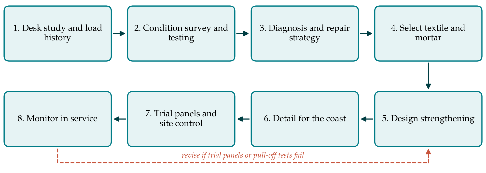
3.1. Step 1: Desk study and load history
The engineer assembles the original drawings and specification if they survive, records of earlier repairs, waterproofing and surfacing, and the loading for which the deck must now be rated. Bridges of this period often carry plain round bars, lapped and hooked, and concrete specified by nominal mix. The desk study fixes what must be confirmed on site and defines the capacity shortfall in terms of the current assessment code (AASHTO, 2018).
3.2. Step 2: Condition survey and testing
The survey combines visual mapping of cracks, staining and spalls with sounding for delamination, a cover survey, half-cell potential mapping to locate areas of probable corrosion activity (ASTM, 2015), carbonation depth, and chloride profiles from dust samples or cores at representative locations. Cores give compressive strength, and exposed bars give the remaining section. Soffit and top surface should both be examined, since chloride may have entered from above through failed waterproofing as well as from the air below.
3.3. Step 3: Diagnosis and repair strategy
The survey results are read together to answer a single question: can the corrosion be controlled by conventional means, so that strengthening is applied to a stable structure? If chloride at bar depth exceeds the level associated with corrosion only locally, removal of contaminated concrete beyond the bars and reinstatement with repair mortar conforming to the repair standard may be enough (CEN, 2005). If contamination is general, patching invites incipient anodes, and the strategy should include cathodic protection or another electrochemical method under the corresponding principle of EN 1504-9. If section loss is so advanced that the existing bars cannot be relied on, a bonded overlay is the wrong tool and replacement of the deck should be considered. The procedure continues only when one of the first two answers applies.
3.4. Step 4: Select textile and mortar
Fibre choice is governed by durability in the alkaline mortar and in the marine atmosphere. Carbon is chemically inert in both. Glass, even of the alkali-resistant type, loses strength with time in a Portland cement matrix through chemical attack and through densification of the matrix around the filaments (Butler et al., 2009), and basalt behaves in a broadly similar way. For a permanent structural retrofit near the sea, carbon is therefore the conservative choice. The mortar should be a proprietary product tested together with the textile as a system, since the tensile and bond properties used in design belong to the pair and not to either component.
3.5. Step 5: Design the strengthening
Flexural design follows plane-section analysis with the textile contributing a tensile force at the soffit. The strain in the textile is limited to the design value derived from coupon or bond tests, and the strain already present in the soffit under permanent load at the time of application is deducted, because the overlay is bonded to a deck that is already carrying its own weight (ACI Committee 549, 2013). The reduced bar areas measured in Step 2 are used for the existing steel. Shear is checked separately; a soffit overlay adds little to the shear capacity of a slab, and a shear deficiency needs its own measure. The designer should also confirm that the unstrengthened deck can carry a defined reduced load without the overlay, so that loss of the system does not lead to collapse.
3.6. Step 6: Detail for the coastal environment
Three details deserve particular attention. First, carbon is electrically conductive and noble to steel, so the textile should not touch the reinforcement or any metallic fixing connected to it; where cathodic protection is installed, the interaction of the conductive mesh with the protection current has to be considered by the specialist designer. Second, the overlay must end on sound concrete with adequate anchorage length, and terminations at edges, joints and drainage outlets should be sealed against water running behind the layer. Third, the surface of the mortar may be given a protective coating to slow further chloride ingress, provided the coating remains permeable to vapour.
3.7. Step 7: Trial panels and site control
Overhead application to a soffit a short distance above tidal water is demanding work. Substrate preparation by water jetting or grit blasting should expose aggregate and remove all weak material, and its adequacy is checked by pull-off tests (CEN, 1999). A trial panel on the structure, made by the operatives who will do the work and tested by pull-off after curing, should precede the main application. During the work the records should cover substrate moisture, mortar batch, layer thickness, textile overlap and curing, with wind and sun protection in place, since thin mortar layers dry quickly and early drying harms bond. Coupons cast on site give the tensile properties actually achieved.
3.8. Step 8: Monitor in service
The half-cell map from Step 2 is repeated after the work at accessible locations, or embedded reference electrodes are installed before the overlay goes on, so that continued corrosion beneath the layer can be detected. Periodic sounding of the overlay for debonding and inspection of terminations complete the regime. The interval should be short in the first years and relaxed only when the readings are stable.
4. Fitting the Procedure to Practice
The sequence is deliberately front-loaded. Most of the cost of getting a retrofit wrong lies in strengthening a deck whose corrosion has not been controlled, and the first three steps are intended to make that error difficult. On a small bridge the survey can be completed in a few days, and its cost is modest beside that of access and traffic management, which are needed in any case. Where the owner's assessment code differs from the one cited here, the load rating in Step 1 and the partial factors in Step 5 change, while the logic of the sequence does not. The procedure also assumes that a system with published tensile and bond data is available on the local market; where none is, qualification testing of the kind described in the design guides has to be added before Step 5.
5. Limitations and What Remains to Be Shown
The procedure has not been applied to a bridge, and nothing in this article should be read as evidence that it works. It joins guidance documents that were written separately, and the joints are where the uncertainty lies. Published flexural tests on strengthened slabs were carried out on sound laboratory concrete under static load (Schladitz et al., 2012; Loreto et al., 2014). A bridge deck is loaded millions of times, and the fatigue behaviour of the bond between a mortar overlay and aged, repaired concrete is not well documented. The review by Koutas et al. (2019) lists durability and long-term behaviour among the open research needs for the material.
Two further matters need study before the procedure could be recommended without reservation. One is the behaviour of the overlay where reinforcement beneath it continues to corrode: whether expansive rust products debond the layer, and whether the layer delays detection. The other is the electrochemical interaction between a carbon textile and the reinforcement, with and without cathodic protection. Application to a monitored structure, with the baseline measurements of Step 2 repeated over several years, would be the natural way to test the proposal.
6. Conclusion
Textile-reinforced mortar suits the conditions of an ageing coastal bridge deck better than resin-bonded systems in several respects, but it strengthens and does not cure. The procedure proposed here places diagnosis and corrosion control ahead of structural design, bases the choice of fibre on durability in an alkaline and saline environment, deducts existing strain and section loss in the design, and builds pull-off testing and electrochemical monitoring into execution and aftercare. It is offered as a framework for engineers and owners to test and improve on real structures.
Conflict of interest
To be declared by the author(s) before publication.
Funding
To be declared by the author(s) before publication.