1. Introduction
Wearable monitors for heart rate, temperature, movement and blood oxygen are now small enough to be sewn into a garment or fixed to the skin as a patch. The radio link is the part that has shrunk least gracefully. An antenna placed a few millimetres from the body works next to a large, lossy dielectric object that detunes it, absorbs part of the radiated power and changes shape as the wearer moves. The standard for wireless body area networks, IEEE 802.15.6, recognises this setting explicitly and defines physical layers for on-body and off-body links in several bands (IEEE, 2012).
Two bands are used far more often than the others in consumer and clinical monitors: the 2.4 GHz band shared with Bluetooth and Wi-Fi, and the 5.8 GHz band, which offers more spectrum and less congestion at the cost of higher path loss. A monitor that covers both can keep a low power link to a phone and offload stored data quickly when a wider channel is available. The microstrip patch suits the task because its ground plane sits between the radiating element and the body, which limits both detuning and absorption (Hall and Hao, 2012).
The literature contains many dual band wearable patches, on textiles, polyimide and other flexible films, and reviews of them are available (Rais et al., 2009). What these papers seldom give is the order of decisions that led to the final geometry. This article sets out such an order as a proposed procedure. It reports no simulation or measurement of its own. Its contribution is the sequence, the reasoning attached to each step and the checks that tell the designer when to move on or go back.
2. Background
Three bodies of established work underlie the procedure: the theory of the microstrip patch, the known ways of obtaining two resonances from one radiator, and the behaviour of antennas close to tissue.
2.1. The patch as a resonant cavity
In its fundamental mode a rectangular patch behaves as a half wavelength resonator, with the wavelength taken in the substrate and corrected for fringing fields at the open edges. The transmission line and cavity models that give the patch length, width and edge impedance are textbook material (Balanis, 2016; Garg et al., 2001), and the closed form expressions for the effective permittivity and length extension of a microstrip line trace back to Hammerstad (1975). The same sources explain the central compromise. A thin substrate of high permittivity gives a small patch with a narrow bandwidth and low efficiency, while a thick substrate of low permittivity gives the opposite (Pozar, 1992). The compromise is one instance of the general limit that ties the bandwidth of an antenna to the volume it occupies (Wheeler, 1947).
2.2. Obtaining two bands
Maci and Biffi Gentili (1997) grouped dual frequency patches into three families: those that use two orthogonal modes of one patch, those that stack or place side by side several radiating elements, and those that load a single patch reactively with slots, notches, stubs or shorting pins. Reactive loading is the family most used in wearables, since it keeps a single layer and a single feed. A slot cut near a radiating edge lengthens the current path of a higher order mode and pulls its frequency down towards the fundamental, and a shorting pin or wall shifts the fundamental and shrinks the patch. Wong (2002) catalogues these techniques and their effect on size, polarisation and pattern.
2.3. Antennas next to the body
Tissue has a high permittivity and appreciable conductivity at microwave frequencies, and both vary with tissue type and frequency. The parametric models of Gabriel et al. (1996) are the usual source of values for simulation. An antenna without a ground plane loses much of its efficiency when brought close to the skin. A full ground plane reduces the loss, and periodic surfaces placed behind the radiator, such as the high impedance surface of Sievenpiper et al. (1999), reduce it further. Zhu and Langley (2009) applied this idea to a dual band textile antenna and reported lower absorption in the body than for the same radiator without the surface, and Raad et al. (2013) did so on a thin polyimide film for telemedicine use. Absorption is expressed as the specific absorption rate and is limited by the ICNIRP guidelines (ICNIRP, 2020) and by IEEE Std C95.1 (IEEE, 2019).
3. The Proposed Procedure
The procedure has seven steps, drawn in Figure 1. Each step ends in a check, and a failed check sends the designer back to the earliest step whose decision it calls into question. Table 1 lists the steps with the decision taken and the check that closes each one. The sub-sections that follow give the reasoning.
| Step | Decision taken | Closing check |
|---|---|---|
| 1. Requirement | Band edges, bandwidth, pattern direction, body site | Written specification agreed |
| 2. Materials | Dielectric, thickness, conductor type | Permittivity and loss known at both bands |
| 3. Lower band | Patch length and width, feed type, ground size | Free space resonance within the lower band |
| 4. Upper band | Slot, notch or shorting element and its position | Both bands matched, patterns acceptable |
| 5. On-body model | Tissue layers, spacing from skin | Bands held and efficiency acceptable on tissue |
| 6. Bending and exposure | Bend radii and axes, input power | Bands held when bent, absorption below limit |
| 7. Prototype | Fabrication route, phantom, test plan | Measurement agrees with simulation |
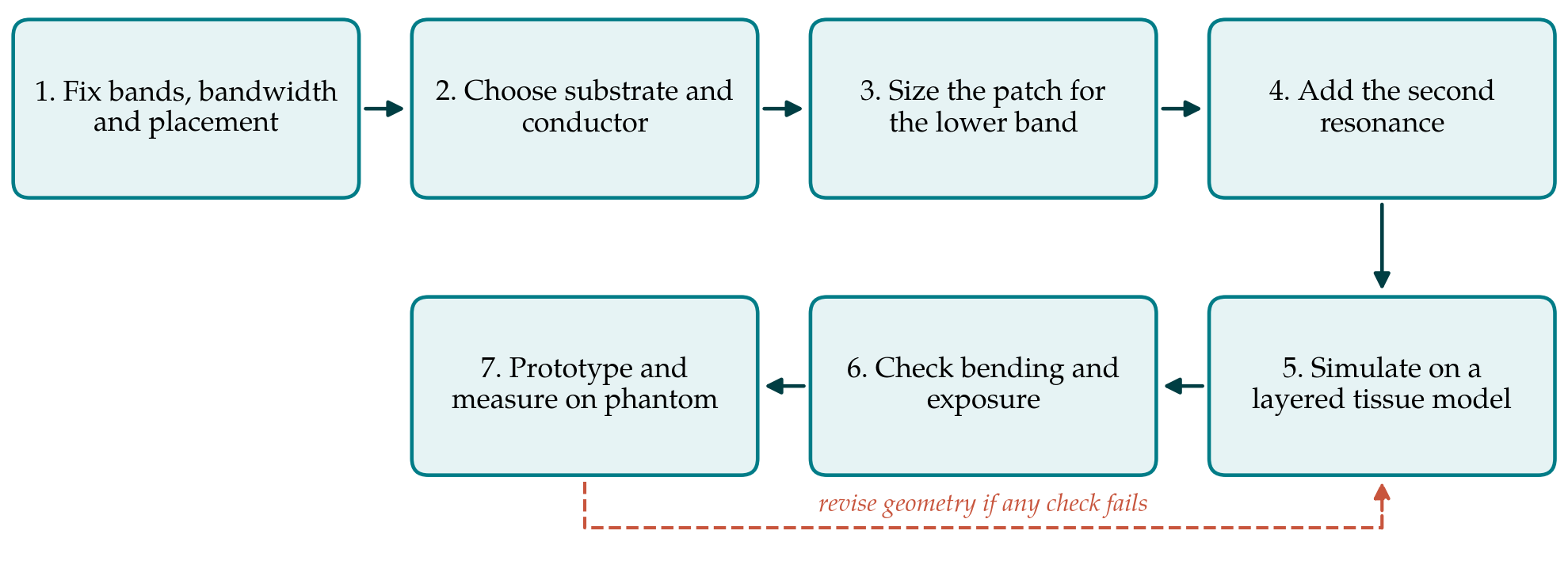
3.1. Step 1: Fix the bands, bandwidth and placement
The designer first writes down what the link needs: the two bands with their edges, the bandwidth in each, the direction of radiation and the place on the body. For the bands discussed here the lower one runs from 2.4 to 2.4835 GHz and the upper one from 5.725 to 5.875 GHz. Placement matters as much as frequency. A chest patch that talks to a phone in a pocket needs a broad pattern directed away from the torso. A wrist device linking to a hub on the waist depends on waves that travel along the body surface, which favours polarisation normal to the skin (Hall and Hao, 2012). The output of the step is a short specification against which every later check is made.
3.2. Step 2: Choose the substrate and conductor
The substrate sets the size, bandwidth, efficiency and comfort of the antenna. The candidates fall into a few groups. Woven and non-woven textiles and felts have a permittivity close to that of air and are a millimetre or more thick, so they give wide bandwidth and good efficiency but a large patch, and their properties change when they absorb moisture (Salonen et al., 2004; Hertleer et al., 2009). Polyimide and similar polymer films are thin, stable and compatible with flexible circuit processing, and give a compact patch whose bandwidth is narrow unless the design compensates for it (Raad et al., 2013). Silicone elastomers stretch, which suits skin patches but makes the resonant frequency depend on strain.
The conductor may be copper foil, conductive fabric, or printed silver ink. Its sheet resistance and its tolerance of repeated flexing should be known before the geometry is fixed, because a lossy or cracked conductor lowers efficiency in a way that no later tuning recovers. The step closes when the permittivity and loss tangent of the chosen material have been measured or taken from a trustworthy source at both bands, not at a single low frequency.
3.3. Step 3: Size the patch for the lower band
With the substrate chosen, the textbook design equations give a starting width and length for the fundamental mode at the centre of the lower band (Balanis, 2016). The feed is chosen at this point. An inset microstrip line keeps the antenna in one plane and suits printed fabrication. A coaxial probe is easier to match but adds a rigid connector under the patch, which is seldom acceptable on the body. The ground plane should extend beyond the patch on all sides by several substrate thicknesses, because it is the ground plane that isolates the radiator from the tissue. The check is a first full wave simulation in free space showing resonance in the lower band with an acceptable match.
3.4. Step 4: Add the second resonance
The second band is obtained by perturbing the patch sized in Step 3. The procedure recommends starting with a single slot, U shaped or a pair of narrow slots parallel to the radiating edges, because its length and its distance from the edge act on the upper resonance far more than on the lower one. The two bands can then be tuned almost independently, which shortens the search (Maci and Biffi Gentili, 1997; Wong, 2002). A shorting element is added only if the patch is still too large for the housing, since it reduces gain and tilts the pattern. The check has two parts: the reflection coefficient must stay below the chosen threshold across both bands, and the pattern in the upper band must still point away from the ground plane without a null at broadside, which is a known hazard of higher order modes.
3.5. Step 5: Simulate on a layered tissue model
The antenna is next placed over a flat model of skin, fat and muscle with dielectric properties taken from Gabriel et al. (1996) at each band, at the spacing the product will have in use, including any fabric or adhesive layer. Three quantities are read from the simulation: the shift in each resonance relative to free space, the radiation efficiency, and the front to back ratio. If the bands move out of specification the geometry is retuned on the tissue model and not in free space, since the body is the operating environment. If efficiency is poor, the usual remedies are a larger ground plane, a thicker substrate, or a periodic backing surface of the kind used by Zhu and Langley (2009).
3.6. Step 6: Check bending and exposure
A flexible antenna will be bent, and bending along the resonant length changes the effective length of the patch more than bending across it. The model is therefore wrapped around cylinders with radii that represent the intended site, an arm and a torso for instance, along both principal axes, and the reflection coefficient is recomputed. Published work on textile patches indicates that the shift is modest for gentle curvature and grows as the radius approaches the patch dimensions (Salonen et al., 2004). A design whose bands are too narrow to absorb the shift goes back to Step 2 for a thicker or lower permittivity substrate.
Exposure is checked in the same model. The specific absorption rate, averaged over the mass prescribed by the applicable guideline, is computed at the highest power the radio can deliver and compared with the limit for local exposure of the general public (ICNIRP, 2020; IEEE, 2019). The comparison must use the limit and averaging mass of the jurisdiction in which the product will be sold, since these differ between regulators.
3.7. Step 7: Prototype and measure on a phantom
Only after the six paper steps is a prototype made. The reflection coefficient is measured in free space, on a tissue equivalent phantom and on a volunteer's arm or chest, flat and bent on formers of the radii used in Step 6. Patterns and efficiency are measured in an anechoic or reverberation chamber with the phantom in place. Care is needed with the feed cable, which can radiate and flatter a small antenna; ferrite chokes or a balun reduce the error. The step closes when measurement and simulation agree to within the tolerance set in Step 1, or when the disagreement has been traced to a material property or fabrication detail and the model corrected.
4. Fitting the Procedure to Practice
The order of the steps is the main claim of this article, and two features of it deserve defence. The first is that the body enters at Step 5 and not at Step 3. Starting on tissue from the outset is sometimes advised, but a free space design converges faster and gives a clean reference against which the effect of the body can be seen. The second is that bending is examined before any prototype is built. Bending failures usually force a change of substrate, and a change of substrate invalidates every dimension chosen after Step 2, so it is cheaper to discover them in simulation.
Practical constraints will reshape some steps. A team without a chamber can still complete Steps 1 to 6 and the reflection measurements of Step 7. Products that are washed need an added check of performance after laundering cycles, a matter treated in the textile antenna literature (Hertleer et al., 2009).
5. Limitations and What Remains to Be Shown
The procedure is proposed and has not been validated here. No antenna was designed with it for this article, so nothing can be said about how many iterations it saves or how close a first prototype made under it comes to its specification. A fair test would give the same requirement to designers working with and without the procedure and compare the number of simulation and fabrication cycles each needs. A second test would apply it across substrates of very different thickness and permittivity to find where its recommendations, the single slot in particular, stop working.
Several simplifications should be kept in view. A flat layered tissue model ignores the curvature and movement of real limbs. Dielectric data for tissue are averages, and individuals differ. The flexible materials themselves age, crease and take up sweat, and their properties at 5.8 GHz are less well documented than at lower frequencies. None of these removes the need for measurement on people, under ethical approval where required, before a medical product is released.
6. Conclusion
A compact dual band patch for a body worn monitor can be reached by a fixed sequence of decisions: requirement, materials, lower band, upper band, tissue, bending and exposure, prototype. Each rests on established theory or published wearable antenna work, and each ends in a check that either releases the designer to the next step or sends the design back. The sequence is offered as a working method for teaching and for small design teams. Whether it shortens development in practice is an empirical question that remains open.
Conflict of interest
To be declared by the author(s) before publication.
Funding
To be declared by the author(s) before publication.