1. Introduction
Modern wind turbines regulate power and limit loads by rotating each blade about its long axis. The blade is carried on a pitch bearing, in most designs a large grease-lubricated slewing bearing with two rows of balls in four-point contact, which transmits the full bending moment of the blade root to the hub (Burton et al., 2011; Harris et al., 2009). Unlike the bearings of a gearbox or generator, a pitch bearing never completes continuous revolutions in service. It adjusts by a few degrees, holds position, and adjusts again, while the loads on it vary with every rotation of the rotor.
This duty has well-recognised tribological consequences. Rolling elements that return repeatedly to the same positions on the raceway cannot draw in lubricant as they would in continuous rotation, and the contacts are prone to wear damage at spacings equal to the rolling element pitch (Kotzalas and Doll, 2010). Control strategies that pitch each blade individually to reduce structural loads (Bossanyi, 2003) increase the number of small oscillations considerably. When a pitch bearing shows roughness, rising friction torque or grease discoloured by wear debris early in its life, the operator needs to know why before deciding whether to replace like with like.
This article proposes a procedure for that investigation. It is written for the case in which fretting corrosion is suspected, and it is designed so that the suspicion is tested against the alternatives. No actual failure is described. The procedure is drawn from published knowledge and is presented for use and evaluation by others.
2. Background
Fretting denotes damage at an interface subjected to small-amplitude oscillatory relative motion. Tomlinson (1927) gave the first systematic account of the rusting of steel surfaces in nominally static contact, and Waterhouse (1972) established fretting corrosion as the term for fretting wear in which oxidation of the debris is prominent. On steel in air the characteristic product is a fine reddish-brown oxide. Vingsbo and Söderberg (1988) showed that the nature of the damage depends on the displacement amplitude through distinct regimes: stick, mixed stick-slip, in which cracking predominates, and gross slip, in which wear predominates.
2.1. False brinelling and fretting corrosion in rolling bearings
In rolling bearings the same family of damage appears on raceways as depressions at ball or roller spacing. Almen (1937) studied the phenomenon in bearings subjected to vibration without rotation and named it false brinelling, to distinguish it from true brinelling, the plastic indentation of the raceway by overload. Later authors have drawn a further distinction. Godfrey (2003) and Errichello (2004) describe false brinelling as mild wear occurring under boundary lubrication, leaving polished depressions with dark debris, and fretting corrosion as the more severe damage that follows once lubricant is excluded from the contact, with reddish-brown oxide and rough, pitted surfaces.
Standards use the words differently again. ISO 15243 classifies both under frictional corrosion and reserves fretting corrosion for damage at fit surfaces, such as those between a ring and its shaft or housing, while applying false brinelling to rolling element and raceway contacts (ISO, 2017). An investigation report should therefore state which definitions it follows. In this article fretting corrosion is used in the sense of Godfrey and Errichello: oxidative fretting wear of a raceway contact from which lubricant has been displaced.
2.2. Oscillating duty and life calculation
Rating life according to ISO 281 assumes continuous rotation and failure by subsurface fatigue (ISO, 2007). Methods for adapting it to oscillating bearings exist and are applied to pitch bearings in the design guideline of Harris et al. (2009), which also warns that for small oscillation angles wear damage and not fatigue may limit life. Schwack et al. (2016) compared the available calculation approaches for bearings under individual pitch control and found that they give markedly different results. A useful descriptor of the motion is the ratio of the distance travelled by the rolling element on the raceway to the width of the Hertzian contact. When it is small, part of the contact is never uncovered and cannot be re-lubricated, and laboratory work has shown that grease properties strongly affect whether damage develops under such conditions (Schwack et al., 2020). Field oscillations are irregular, and counting methods have been proposed to reduce a pitch-angle history to cycles of defined amplitude (Stammler et al., 2018).
3. The Proposed Investigation Procedure
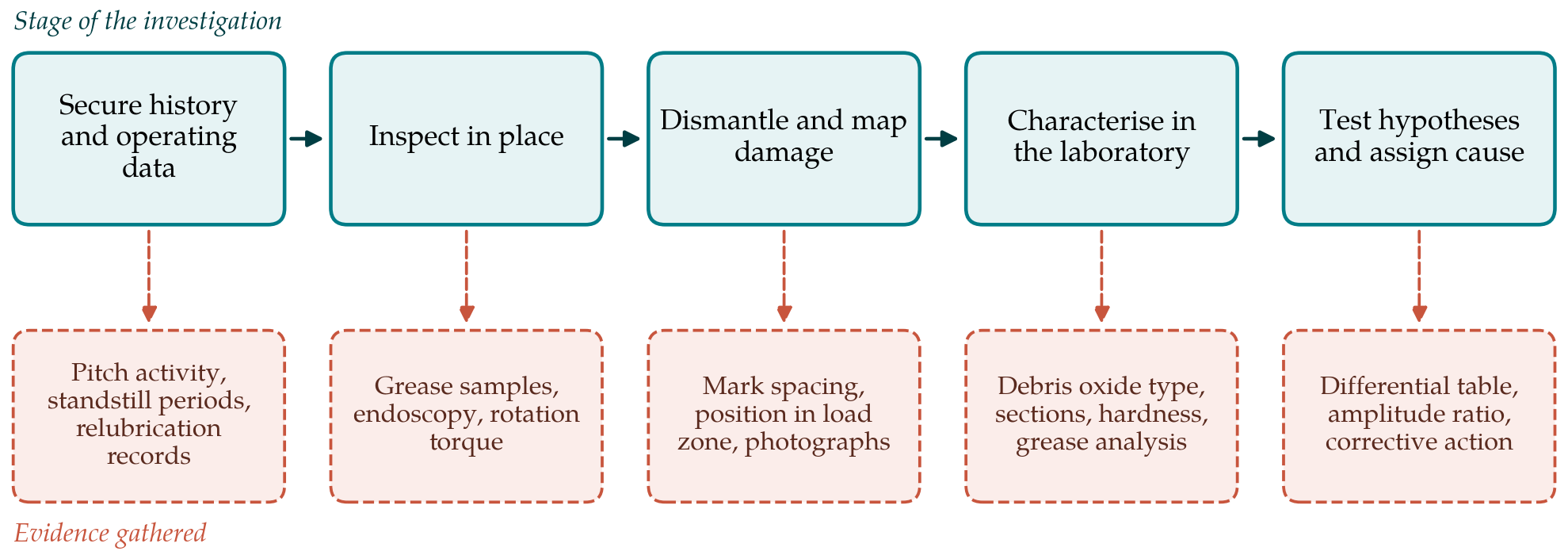
The procedure follows the general sequence of engineering failure analysis, in which evidence is preserved and recorded before anything is disturbed and destructive examination comes last (Becker and Shipley, 2002). It has five stages, shown in Figure 1 together with the evidence each is meant to yield.
3.1. Stage 1: Secure the history and operating data
The investigation begins away from the bearing. The turbine controller log is exported for as long a period as is retained, with pitch angle, pitch rate, rotor speed, wind speed and operating state. From it the investigator derives how much of the time the blade stood still, in which pitch positions it dwelt, and the distribution of oscillation amplitudes, using a counting method of the kind described by Stammler et al. (2018). Maintenance records supply the grease type, relubrication intervals and quantities, and whether the automatic lubrication system, if fitted, was functioning. Transport and storage history is requested as well, since standstill marks can originate before commissioning.
3.2. Stage 2: Inspect the bearing in place
Before the bearing is removed, grease is sampled from several positions around the circumference and from both rows, with the positions recorded, and the colour and consistency of each sample noted. Where access ports allow, the raceway is viewed by endoscope. Rotation torque is measured over the pitch range if the turbine permits, and the bolted joints to hub and blade are checked for loss of preload, because movement at those joints is itself a possible site of fretting. The pitch angle of the bearing as found is marked on both rings so that damage can later be related to the loaded zone.
3.3. Stage 3: Dismantle and map the damage
After removal the bearing is opened with care not to add marks, and rings, rolling elements, cages or spacers and seals are photographed before cleaning. The raceways are then mapped. For each damaged area the record gives its angular position, its size and shape, its location across the raceway profile and the spacing to its neighbours. Spacing equal to the rolling element pitch indicates damage formed without net rotation. The distribution around the circumference is compared with the load zone expected from blade root bending and with the dwell positions found in Stage 1. Damage on the ring fits and bolt-hole faces is recorded separately from raceway damage.
3.4. Stage 4: Characterise surfaces, debris and grease
Laboratory work is aimed at the features that separate one damage mode from another. Marks are examined by optical and scanning electron microscopy and their profiles measured, to establish whether material has been removed by wear or displaced plastically with raised shoulders. Debris from the marks and from the grease is analysed to identify the oxide, since reddish-brown haematite is associated with fretting corrosion and dark magnetite-rich debris with lubricated false brinelling (Godfrey, 2003). Metallographic sections through selected marks show whether there is subsurface cracking or microstructural alteration, and hardness is checked against the specification. The grease samples are analysed for iron content, water, base oil content and consistency, and compared with fresh grease of the same type.
3.5. Stage 5: Test competing hypotheses and assign cause
The evidence is then set against each candidate damage mode in turn. Table 1 lists the modes that should be considered and the features that distinguish them. A mode is accepted only if the surface evidence, the debris and the operating history agree. Fretting corrosion of the raceway, in the sense used here, is supported when marks at rolling element pitch show material loss with rough, pitted floors and reddish-brown oxide, when the grease near the marks is depleted of oil or displaced, and when the history shows long periods of small oscillation or standstill under varying load.
| Damage mode | Surface appearance | Debris and grease | Supporting history |
|---|---|---|---|
| Fretting corrosion | Rough, pitted marks at element pitch; material removed | Reddish-brown oxide; grease dry or displaced | Small oscillations or standstill; poor relubrication |
| False brinelling | Polished shallow depressions at element pitch | Dark debris; lubricant still present | Vibration at standstill; early in life or transport |
| True brinelling | Indentations with raised edges; finishing marks preserved in the floor | Little or no debris | Extreme load event; handling or mounting impact |
| Rolling contact fatigue | Spalls with steep edges; not confined to element pitch | Metallic flakes | High cycle count at high contact stress |
| Moisture corrosion | Etched or rusted areas; may follow contact lines | Rust; water in grease | Seal damage; condensation during standstill |
| Fit-surface fretting | Damage on ring seats and bolted faces | Red oxide at the joint | Loss of bolt preload; flexible supporting structure |
Identifying the mode is not the same as identifying the cause. For fretting corrosion the contributing causes to examine are the amplitude of motion relative to the contact width, the ability of the grease to return to the contact, the frequency and adequacy of relubrication, and deformation of the rings by a compliant hub or blade root that alters the load distribution. Each is assessed from the Stage 1 data and the bearing geometry. The outcome is a statement of the most probable cause with the evidence for and against it, and a corrective action that follows from that cause, such as a change of grease, the introduction of periodic larger pitch movements to redistribute lubricant, or a revised relubrication regime.
4. Fitting the Procedure to Practice
Access is the main practical constraint. A pitch bearing can weigh several tonnes and its removal requires a crane and a weather window, so Stages 1 and 2 will often have to support an interim judgement before the bearing is available. They are designed to be useful alone: grease samples with red oxide and a controller history dominated by small-amplitude motion already make fretting corrosion a strong candidate. Where several turbines of one type are affected, the first bearing removed should be examined in full and the findings used to decide which stages can be shortened for the rest.
Laboratory reproduction may be added as a sixth stage where the stakes justify it. Standard grease tests for fretting wear protection, such as ASTM D4170 (ASTM International, 2016), rank lubricants under a fixed oscillating condition, and tests on scaled bearings under conditions derived from the field history have been reported (Schwack et al., 2020). Agreement between marks produced in such tests and those found in the field strengthens the diagnosis and gives a means of checking a proposed remedy before it is applied to a fleet.
5. Limitations and What Remains to Be Shown
The procedure is proposed and has not been validated on field failures in this article. Its discriminating features are taken from the literature, and their reliability in large slewing bearings is not fully established. Colour of debris, in particular, is a helpful but imperfect guide: mixed oxides are common, false brinelling is widely held to progress into fretting corrosion as lubricant is lost, and a bearing examined late may show fatigue spalls that started at earlier wear marks. The investigator may be able to identify only the final state with confidence.
What needs to be shown is whether investigators applying the procedure independently to the same bearing reach the same conclusion, and whether corrective actions derived from it prevent recurrence. Both questions can be addressed by operators and bearing manufacturers who hold collections of failed bearings with known histories. Design standards for turbines set general requirements for components and their loads (IEC, 2019), but they do not prescribe how pitch bearing damage is to be investigated, so an agreed and tested procedure would fill a real gap.
6. Conclusion
Premature pitch bearing failure with regularly spaced raceway marks admits several explanations, and the remedy depends on choosing correctly among them. The procedure proposed here gathers operating history before physical evidence, maps damage before cleaning and sectioning, concentrates laboratory work on the features that separate fretting corrosion from false brinelling, overload indentation, fatigue and moisture corrosion, and requires that surface, debris and history agree before a mode is named. It then asks separately what caused that mode. The approach rests on established fretting research and on published studies of oscillating bearings, and it now needs to be tried on documented cases.
Conflict of interest
To be declared by the author(s) before publication.
Funding
To be declared by the author(s) before publication.