1. Introduction
A malunited fracture or a developmental deformity is seldom confined to one plane. Angulation in the coronal and sagittal planes usually coexists with rotation and translation, and the true deformity lies in an oblique plane that no standard radiograph shows directly. The principles for analysing such deformities from radiographs are well established (Paley, 2002), but carrying out a multiplanar correction freehand, with wires and an image intensifier, depends heavily on the surgeon's spatial judgement.
Three-dimensional planning from computed tomography (CT) offers a different route. The deformed bone is modelled, compared with a template (usually the mirrored opposite side), and the osteotomy is simulated on screen. A patient specific guide then transfers the simulated cut and the planned position of the fragments to the patient. The approach was developed for malunions of the forearm and has since been applied around the knee and elsewhere (Murase et al., 2008; Victor and Premanathan, 2013). Systematic reviews of three-dimensional printing in surgery list surgical guides among its commonest uses and report shorter operating time and better accuracy as the usual claimed benefits, with cost and production time as the usual drawbacks (Tack et al., 2016; Martelli et al., 2016).
Producing the guides inside the hospital addresses those two drawbacks and brings the surgeon closer to the design. It also makes the hospital a manufacturer. This article proposes a procedure by which an orthopaedic department can do this in an orderly way. It describes a method; it does not report results, and the procedure has not been validated here.
2. Background
A cutting guide is a negative of a chosen area of bone surface, extended into a body that carries slots for the saw blade and sleeves for drills or wires. Its accuracy depends on a chain of steps, each of which adds error: the resolution of the scan, the fidelity of the segmentation, the quality of the plan, the dimensional accuracy of the printer, and the surgeon's ability to seat the guide on a bone surface that has been cleared of soft tissue. The radiological literature on medical printing describes this chain and the points at which it commonly fails (Mitsouras et al., 2015), and guidance from the Radiological Society of North America sets out expectations for image quality, segmentation and quality control of printed models (Chepelev et al., 2018).
The regulatory position differs between jurisdictions and should be established locally before any guide is used. In the European Union, the Medical Devices Regulation permits health institutions to manufacture and use devices in house under the conditions of its Article 5(5), which include an appropriate quality management system, documentation of the design and manufacturing process, and a justification that the need cannot be met by an equivalent device on the market (European Union, 2017). In the United States, the Food and Drug Administration has issued guidance on technical considerations for additively manufactured devices (FDA, 2017). A cutting guide is in contact with tissue for a short period and must be sterile, so biological evaluation of the material and validation of the sterilisation cycle are unavoidable parts of the task (Christensen and Rybicki, 2017).
3. The Procedure
The procedure has seven steps, shown in sequence in Figure 1. The paragraphs that follow describe each step; the checks and records attached to them are gathered in a table further on.
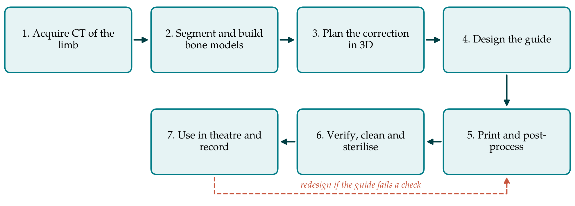
3.1. Step 1: Image acquisition
A CT scan is obtained of the deformed bone and, where a mirrored template is to be used, of the opposite side. Thin slices are needed over the region where the guide will sit, because the fitting surface can be no more accurate than the scan. For long-bone deformity, the joints above and below should be included, at lower resolution if dose is a concern, so that the mechanical axes can be reconstructed. The scanning protocol should be written down and agreed with radiology so that every case is imaged the same way, and metal artefact from existing implants should be anticipated, since it degrades the surface on which the guide depends.
3.2. Step 2: Segmentation
Segmentation converts the image volume into a surface model of the bone. Thresholding on bone density followed by manual correction is the usual method, and open-source software such as 3D Slicer is capable of it (Fedorov et al., 2012). The operator must separate adjacent bones at joints, close defects where cortical bone is thin, and avoid excessive smoothing, which removes exactly the surface detail that makes a guide fit in only one position. The resulting mesh should be overlaid on the original images and checked slice by slice by a second person before it is used for planning.
3.3. Step 3: Three-dimensional planning
Planning is a clinical act and belongs to the operating surgeon. The deformity is quantified by aligning the proximal part of the deformed bone with the template and measuring the displacement of the distal part, or by reconstructing joint orientation lines in three dimensions in the manner taught for radiographic analysis (Paley, 2002). The level and type of osteotomy are chosen, the cut is simulated, and the fragments are moved to the corrected position. The planner checks bone contact, any lengthening or shortening, the effect on neighbouring joints, and whether the chosen plate will fit the corrected bone. A mirrored template is a convenience and not a truth: side-to-side differences exist in normal skeletons, and bilateral deformity removes the reference altogether.
3.4. Step 4: Guide design
The guide is designed on the planned model. Its fitting surface should cover an area with enough contour to lock it in place, lie within the planned surgical exposure, and avoid tendon insertions and periosteum that will not be stripped. A reliable strategy, described in the forearm literature, is to drill the screw holes for the plate through the guide before the osteotomy is made, so that fixing the plate to the predrilled holes afterwards produces the planned reduction (Murase et al., 2008; Kunz et al., 2013). Saw slots must allow for blade thickness and be long enough to control the blade without preventing irrigation. Each guide should carry an embossed identifier and side marking. The design is finished only when the surgeon has reviewed and signed it.
3.5. Step 5: Printing and post-processing
The printing process and material are chosen together, using the process categories of the terminology standard (ISO/ASTM, 2021). Vat photopolymerisation with a resin for which the supplier documents biocompatibility testing for short-term tissue contact, and powder bed fusion of polyamide, are the processes most often reported for guides. Material extrusion on a hobby printer is cheaper but yields parts whose porosity and tolerance of sterilisation need particular scrutiny. The supplier's instructions for washing, curing and support removal form part of the validated process and should be followed exactly, because incomplete curing alters both dimensions and biological safety. A bone model of the fitting area is usefully printed alongside each guide.
3.6. Step 6: Verification, cleaning and sterilisation
Before release, each guide is inspected for defects, measured at predefined points against the design, and test-fitted on the printed bone model. Slot width and sleeve diameter are checked with the actual blade and drill. The guide then enters the hospital's sterile services pathway. The sterilisation method must be one for which the material is rated and for which the hospital has a validated cycle; for moist heat the governing standard is ISO 17665 (ISO, 2006). Heat can distort printed polymers, so dimensional checks should be repeated on a sample of sterilised parts when the process is first set up. Table 1 sets out the check and the record for each step.
| Step | Typical source of error | Check before proceeding | Record kept |
|---|---|---|---|
| 1. Imaging | Thick slices, movement, metal artefact | Protocol followed; images reviewed | Scan protocol and date |
| 2. Segmentation | Over-smoothing; fused adjacent bones | Overlay of mesh on images by second person | Software version, settings, model file |
| 3. Planning | Unsuitable template; unrealistic correction | Surgeon reviews plan and plate fit | Signed plan with measurements |
| 4. Guide design | Ambiguous seating; inaccessible surface | Fit on virtual and printed bone model | Design file and approval |
| 5. Printing | Warping, incomplete cure, wrong material | Visual and dimensional inspection | Printer, material lot, parameters |
| 6. Sterilisation | Heat distortion; residual contamination | Validated cycle; fit rechecked | Cycle record and release |
| 7. Use in theatre | Soft tissue under guide; guide shifts | Seating confirmed before pinning | Operative note and imaging |
3.7. Step 7: Intraoperative use and documentation
In theatre the bone is exposed over the planned area and cleared of soft tissue. The guide is seated and its fit confirmed by eye and by feel, with the sterile bone model available for comparison, before it is pinned. If the guide does not seat unambiguously, it should be abandoned and the operation completed by conventional means; the surgeon must always be prepared for that. After fixation, the result is checked with the image intensifier in the usual way. The operative note records the guide identifier and any deviation from the plan, and postoperative imaging is compared with the plan as a routine measure of quality.
4. Fitting the Procedure to a Hospital Department
The procedure needs people before it needs machines. A surgeon who plans, an engineer or technologist who segments and designs, and a named person responsible for quality are the minimum, and the roles should be separated so that no one checks their own work. A quality management system is required under the European in-house exemption, and ISO 13485 is the recognised model for it (ISO, 2016). In practice this means written procedures for each step, controlled versions of software and design files, traceability from the patient to the material lot, training records, and a route for reporting and investigating failures.
The economic case should be made honestly. Published analyses suggest that guides and anatomical models can save operating time, and that the value of that time can offset production costs (Ballard et al., 2020), but a department printing a small number of guides a year carries fixed costs in staff time, software, validation and maintenance that a simple cost per print conceals. Collaboration with a university engineering department or a regional hub may suit low-volume units better than independent production. Departments should also decide in advance which cases justify a guide. Simple uniplanar corrections gain little; multiplanar malunions and osteotomies close to joints are where the planning effort is most likely to be repaid (Hoekstra et al., 2016).
5. Limitations and What Remains to Be Shown
What is described here is a proposed procedure, assembled from the literature and from standards. It has not been tested in this article. A department adopting it would need to establish at least four things in its own setting before clinical use and during it. The first is dimensional accuracy: that printed and sterilised guides match their design within a stated tolerance. The second is transfer accuracy: that the correction achieved, measured on postoperative CT or calibrated radiographs, agrees with the plan. Sawbone or cadaveric trials are the appropriate first test. The third is safety, including sterility assurance and the absence of material-related reactions. The fourth is benefit to the patient, which is the hardest to show, because better radiographic accuracy does not by itself prove better function.
The published evidence for guides in deformity surgery consists mainly of case series and technical reports, and comparative studies against conventional technique are few (Tack et al., 2016). The procedure also depends on judgement at several points that no checklist replaces: the choice of template, the decision that a segmentation is good enough, and the decision in theatre to trust or discard a guide. It is confined to single-use polymer cutting and drilling guides and does not extend to printed implants, which raise different and stricter requirements.
6. Conclusion
Designing and printing patient specific cutting guides within a hospital is technically within reach of an orthopaedic department with access to CT, suitable software and a qualified printer. What makes it safe is the discipline around the technology: a fixed imaging protocol, independent checking of the segmentation, a surgeon-owned plan, a design that seats in one position, a validated route through printing and sterilisation, and records that tie every guide to a patient. The seven-step procedure proposed here is intended as a starting framework for departments to adapt, test on models and audit against their own results before and after they bring it into clinical use.
Conflict of interest
To be declared by the author(s) before publication.
Funding
To be declared by the author(s) before publication.