1. Introduction
In a battery-powered or always-on system the memory macros are rarely idle in the sense of being switched off. They retain state, and every cell conducts a small current whether or not it is addressed. As thresholds were lowered with supply voltage, that current grew to the point where static power became a first-order design constraint (Roy et al., 2003). Designers have several remedies: high-threshold cell devices, a lowered standby supply, a raised cell ground, and body biasing. Only the last three can be adjusted after manufacture.
Body bias was applied to logic first, in the variable-threshold scheme of Kuroda et al. (1996), and was made adaptive by Tschanz et al. (2002), who used it to pull dies from the fast, leaky end and the slow end of the process distribution towards the centre. Its use in memory raises additional questions, because a memory cell is a ratioed circuit whose stability depends on the relative strengths of its transistors. This note summarises the technique as it applies to an embedded six-transistor macro. It is a commentary on published principles and contains no original measurements.
2. Leakage Paths in the Cell
A six-transistor cell in the hold state has three devices that are nominally off with the full supply across them: one pull-down, one pull-up and one access transistor connected to a precharged bit line. Each conducts subthreshold current, which depends exponentially on threshold voltage and rises steeply with temperature. Gate tunnelling through thin oxides and band-to-band tunnelling at the reverse-biased drain junctions add to it, together with gate-induced drain leakage (Roy et al., 2003). The mix differs between technologies, and the split matters here because body bias reduces only the subthreshold component and makes the junction component worse.
3. How Body Bias Acts on the Macro
Reverse-biasing the body of a bulk transistor widens the depletion region under the channel and raises the threshold voltage through the body effect; forward bias lowers it (Taur and Ning, 2009). Since subthreshold current falls by roughly a decade for each increment of threshold equal to the subthreshold swing, a modest reverse bias can cut it substantially. The same bias increases the field across the drain junction, and with it band-to-band tunnelling. Total leakage therefore passes through a minimum at some reverse bias and rises beyond it. Keshavarzi et al. (2001) showed that this optimum bias becomes smaller and the achievable saving shrinks as bulk technology scales, because the body effect weakens in short channels and junction tunnelling grows.
In a memory the threshold shift also moves the margins of the cell. Raising the n-channel threshold weakens the access and pull-down devices, which lowers cell current and slows the read, yet it tends to improve hold stability as measured by the static noise margin of Seevinck et al. (1987). Forward bias does the opposite. Because random threshold mismatch between neighbouring transistors already sets the failure rate of large arrays (Bhavnagarwala et al., 2001), a bias that helps leakage must be checked against the read, write, access-time and hold failure mechanisms together, at the bias and temperature where each is worst.
4. Making the Bias Adaptive
A fixed reverse bias chosen for the leakiest die over-biases typical dies and may cost slow dies their read margin. An adaptive scheme sets the bias per die, and possibly per temperature. Figure 1 shows the loop in outline. A monitor senses a quantity that tracks the threshold voltage of the die, such as the leakage of a replica column or of the array itself, or the delay of a replica path built from cell-like devices. A comparator or a small state machine compares it with a target, and a bias generator moves the well voltage until the two agree. Mukhopadhyay et al. (2007) proposed a memory of this kind, in which an on-chip leakage monitor identifies the process corner and selects reverse bias for leaky dies and forward bias for slow ones, with the aim of improving yield as well as power.
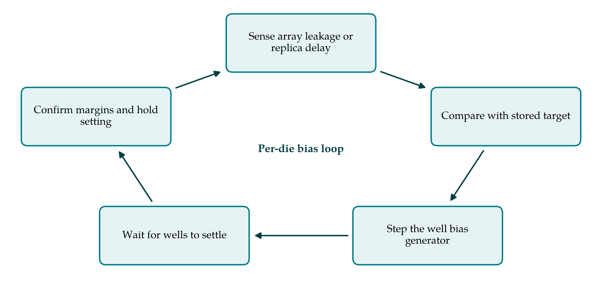
The granularity of the loop is a design choice. One bias for the whole die corrects the die-to-die component of variation and costs a single generator. Separate biases for each macro, or for blocks within a large macro, follow temperature gradients and within-die trends more closely, at the price of well isolation between regions and of more monitors. Random mismatch between neighbouring transistors cannot be corrected by any shared well bias. The update rate is a second choice: a setting found once at test and stored is the simplest, while a loop that reruns when temperature changes tracks the strong temperature dependence of leakage.
Body biasing is one of several standby techniques, and Table 1 sets it beside the alternatives. Lowering the standby supply towards the data retention voltage reduces every leakage component at once, including gate and junction currents (Qin et al., 2004), and is often combined with body bias. Forward bias during access, to recover speed, was examined for logic by Narendra et al. (2003) and is limited by junction conduction and the risk of latch-up.
| Technique | What it changes | Strength | Cost or limit |
|---|---|---|---|
| High-threshold cell devices | Threshold, fixed at manufacture | No circuit overhead | Slower read at all times |
| Fixed reverse body bias | Threshold during standby | Simple control | Wrong setting for dies away from the design corner |
| Adaptive body bias | Threshold, per die and temperature | Tracks process and temperature Tschanz et al., 2002 | Monitor, generator, calibration and test time |
| Lowered standby supply | Voltage across every cell device | Cuts all leakage components Qin et al., 2004 | Hold margin shrinks near the retention voltage |
| Raised cell ground | Source voltage of pull-down devices | Adds body effect to reduced cell voltage | Wake-up time; reduced hold margin |
5. Overheads and the Role of Device Architecture
The overheads are physical and are easy to underestimate. Independent bias of n-channel bodies in a bulk process requires a triple-well structure, and the wells of a dense array must be tapped often enough for the bias to reach every cell. Reverse bias voltages lie below ground or above the supply and must be made by charge pumps whose own consumption is charged against the saving. The wells of a large macro form a sizeable capacitance, so entering and leaving the biased state takes time and energy, and a frequently accessed macro may never recover the cost.
Two further costs appear only at the level of the product. A bias loop adds states to production test, since the macro must be shown to work at every setting the loop may choose and the monitor itself must be calibrated. And the bias generators, level shifters and well contacts are additional circuits that must meet the same reliability and latch-up rules as the rest of the design.
The device architecture decides how much is available. In fully depleted silicon-on-insulator with a thin buried oxide, the well under the device acts as a back gate; there is no junction between body and source to limit the range, and the threshold can be moved widely in either direction (Planes et al., 2012). In fin and gate-all-around transistors the gate controls the channel so thoroughly that the substrate has almost no influence, and body biasing is largely ineffective. The technique therefore belongs to planar bulk and fully depleted processes.
6. Measuring and Reporting a Saving
Because the saving depends so strongly on conditions, a figure quoted without them means little. A useful report states the temperature, since subthreshold leakage and therefore the benefit of reverse bias are far larger hot than cold; the supply voltage in standby; the process corner or the position of the measured dies in the lot distribution; and whether peripheral circuits are included. It gives leakage as a function of bias so that the minimum is visible, includes the current drawn by the bias generators and monitors, and shows that the macro still passes read, write and retention tests at the chosen bias. Finally, it reports the time and energy of the transition, from which the shortest idle period that justifies biasing follows. Where figures from different designs are compared, the fairest basis is leakage per bit at a stated temperature and standby voltage with the bias overhead included, because array size and peripheral design otherwise obscure the effect of the bias itself.
7. Conclusion
Adaptive body biasing reduces the standby leakage of an embedded memory by raising thresholds only as far as each die and temperature require, and it can be reversed to recover speed or margin. Its benefit is bounded by junction tunnelling, by the stability margins of the cell and by the overhead of wells and generators, and it is of little use in fin-based processes. Claims of leakage reduction are best judged by whether they state their conditions and account for those overheads.
Conflict of interest
To be declared by the author(s) before publication.
Funding
To be declared by the author(s) before publication.