1. Introduction
Fibre Bragg gratings have moved from the optics laboratory to the bridge deck within a single generation. The grating itself, a periodic modulation of refractive index written into the core of a single-mode fibre with ultraviolet light, became practical once side-writing through the cladding was demonstrated (Meltz et al., 1989), and its use as a sensor followed quickly (Kersey et al., 1997; Rao, 1997). For the engineer responsible for a large structure the attractions are easy to list. The measurand is encoded in wavelength, so the reading does not depend on optical power or connector loss. Many gratings can be read along one fibre. The sensing element is passive, immune to electromagnetic interference and lightning, and can sit kilometres from its interrogator (Li et al., 2004; Majumder et al., 2008).
The same physics that makes the grating a good strain gauge makes it a good thermometer. A change in temperature alters both the refractive index of the glass and the period of the grating, and the reflected wavelength moves exactly as it would under mechanical strain. Near 1550 nm a bare silica grating shifts by roughly 1.2 pm for each microstrain and by about 10 pm for each degree Celsius, so one degree of unaccounted temperature change reads as something like eight to ten microstrain. A bridge member in temperate climates experiences tens of degrees between a winter night and a summer afternoon, while the live-load strain of interest in a girder is often a few tens of microstrain. Without compensation the quantity being sought is buried under the quantity being ignored.
This article reviews how that problem has been addressed. It is concerned less with listing every sensor configuration that has been published than with the assumptions each class of method makes and whether those assumptions hold on a real bridge, where the temperature field is neither uniform nor steady and the monitoring period is measured in decades.
2. Scope and Approach
The article is a narrative review of the published literature. It draws on the foundational papers on grating sensors, on the body of work on discriminating strain from temperature that appeared mainly in optics and measurement journals during the 1990s and early 2000s, on standard monographs (Othonos and Kalli, 1999; Glisic and Inaudi, 2007), and on reports of instrumented bridges. No claim of exhaustive coverage is made, and no formal search protocol was followed. The sources were chosen because they are widely cited and because each illustrates a distinct principle. Distributed sensing by Brillouin or Rayleigh scattering faces a related cross-sensitivity but is outside the scope, as are gratings in polymer fibre.
3. Where the Thermal Response Comes From
Confusion about compensation often begins with a failure to say what is to be removed. At least three distinct thermal effects reach the interrogator, and they do not all deserve the name of error.
3.1. The intrinsic response of the grating
A uniform grating reflects a narrow band centred on the Bragg wavelength, equal to twice the product of the effective refractive index of the guided mode and the grating period (Hill and Meltz, 1997). Axial strain lengthens the period and, through the photo-elastic effect, lowers the index; the two partly cancel, and the fractional wavelength shift is about 0.78 of the applied strain for standard germanosilicate fibre. Temperature acts through the thermal expansion of silica, which is very small, and through the thermo-optic coefficient, which is more than ten times larger and therefore dominates. The result is a fractional shift of several parts per million per degree in a free fibre. This intrinsic term is always present, is nearly linear over the ambient range, and is a pure artefact from the point of view of strain measurement.
3.2. Expansion of the host member
A grating bonded to steel or embedded in concrete is forced to follow the thermal expansion of its host, whose coefficient is some twenty times that of silica. The grating then registers a real strain, the free thermal strain of the member, on top of its intrinsic response. Whether this is wanted depends on the purpose. An engineer tracking the movement of an expansion joint needs total strain. An engineer assessing stress needs only the part of the strain that is resisted, and must subtract the free thermal expansion. The standard treatments of fibre sensing in civil structures make this distinction between total and mechanical strain explicit (Glisic and Inaudi, 2007), and a compensation scheme that removes one but is reported as if it removed the other is a common source of misread data.
3.3. Thermally induced stress
A statically indeterminate bridge is not free to expand, and a non-uniform temperature profile through the depth of a box girder produces self-equilibrating stresses even in a simply supported span. These strains are mechanical and real. Long-term monitoring has shown repeatedly that the thermal response of a bridge can exceed its response to traffic: the year-long record from the Z24 bridge showed changes in dynamic properties with temperature large enough to mask those of damage unless they were modelled (Peeters and De Roeck, 2001), and strain records from a long-span truss bridge showed temperature-induced strains well above those from daily traffic (Catbas et al., 2008). No sensor-level scheme should remove this component, because it is part of the state of the structure. Its separation from load effects is a problem of interpretation, discussed by Sohn (2007), and is taken up again below.
4. Families of Compensation Method
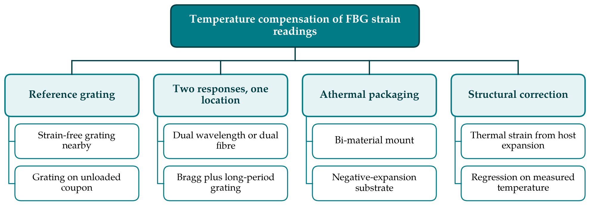
The methods in the literature fall into four families, arranged in Figure 1. The first three act at the sensor and aim at the intrinsic response, with or without the host expansion. The fourth acts on the data and can be directed at any of the three contributions. Table 1 summarises the assumption that each family depends on and the way it most commonly fails in bridge service.
| Family | Key assumption | Typical failure in bridge service | Representative sources |
|---|---|---|---|
| Reference grating | Reference is strain-free and at the same temperature as the active grating | Solar heating of one face; friction or adhesive loads the reference | Kersey et al., 1997 |
| Dual wavelength or dual fibre | Sensitivity matrix is well conditioned and constant | Amplified wavelength noise; coefficients change with ageing | Xu et al., 1994; Jin et al., 1997 |
| Hybrid Bragg and long-period grating | Both elements see the same strain and temperature | Long-period grating disturbed by bending and by the surrounding medium | Patrick et al., 1996 |
| Athermal package | Package expansion cancels the fibre response over the whole range | Residual non-linearity; pre-tension lost through creep | Yoffe et al., 1995 |
| Host-expansion correction | Member temperature and expansion coefficient are known | Gradients through the section; coefficient of concrete varies with moisture | Glisic and Inaudi, 2007 |
| Regression on temperature | Thermal response is stable and well sampled in training data | Damage or bearing restraint alters the thermal response itself | Sohn, 2007 |
4.1. A strain-isolated reference grating
The oldest and still the most widely used approach places a second grating close to the first and shields it from strain, for instance by leaving it loose inside a small tube or by bonding it to a coupon of the host material that carries no load. Its wavelength shift is attributed wholly to temperature and subtracted from that of the strain grating, after scaling by the ratio of the two temperature sensitivities (Kersey et al., 1997). If the reference grating sits on an unloaded piece of the same steel or concrete, the subtraction also removes the free expansion of the host and leaves mechanical strain. The appeal is simplicity and a clear physical meaning. The cost is one extra grating per measurement point, which halves the multiplexing capacity of the fibre, and a dependence on two things that are hard to guarantee: that the reference is truly free of strain for the life of the installation, and that it is at the same temperature as the active grating at every moment.
4.2. Two independent responses at one location
A second family avoids the co-location problem by extracting two measurements with different ratios of strain to temperature sensitivity from essentially the same point, then solving two linear equations for the two unknowns. Xu et al. (1994) superimposed gratings at two widely separated wavelengths and inverted the resulting sensitivity matrix. Patrick et al. (1996) paired a Bragg grating with a long-period grating, whose temperature response is far larger. James et al. (1996) spliced fibres of different diameter so that two adjacent gratings share a temperature response and differ in strain response, and Cavaleiro et al. (1999) did the converse with fibres of different dopant composition. A superstructure grating gives both responses from a single element (Guan et al., 2000), and a rosette of gratings can separate the isotropic thermal term from the strain tensor (Magne et al., 1997).
The limit of all these schemes is numerical. The error analysis of Jin et al. (1997) showed that the uncertainty of the recovered strain depends on how well conditioned the sensitivity matrix is. When the two responses differ only slightly in their ratio of sensitivities, as with two Bragg gratings at different wavelengths in the same fibre, small errors in wavelength measurement are amplified into large errors in strain. Configurations with strongly different responses condition the matrix well but bring broader spectra, harder multiplexing or fragile splices. The survey by Frazão et al. (2005) sets out this trade across many configurations. Few of them have left the laboratory for bridge service, where robustness of the sensing head has counted for more than elegance.
4.3. Athermal packaging
A third route removes the intrinsic response mechanically. In the passive package of Yoffe et al. (1995), developed to stabilise gratings used as telecommunication filters, the fibre is held under tension between two materials of different thermal expansion arranged so that a rise in temperature relaxes the tension by just enough to cancel the thermo-optic shift. Substrates with a negative expansion coefficient achieve the same end. For a strain sensor the idea must be adapted, because the package has to transmit the strain of the structure while cancelling temperature, and the two requirements pull in opposite directions. Athermal designs are therefore found more often in displacement, pressure and load transducers built around gratings than in directly bonded strain gauges. Their compensation is exact only at the design point and depends on a pre-tension that must survive for the life of the device.
4.4. Correction at the level of the structure
The fourth family leaves the sensor alone and corrects the record. In its simplest form the temperature of the member is measured, by a loose grating or a conventional thermometer, and the product of that temperature change and the combined thermal sensitivity of the bonded grating is subtracted. This requires the expansion coefficient of the host, which is well known for structural steel and much less certain for concrete. The statistical form treats the thermal response as a nuisance variable and removes it by regression, principal component analysis or a related method fitted to a baseline period (Sohn, 2007). Such models can absorb the intrinsic response, the host expansion and the thermally induced stress in one step, which is convenient and also dangerous, because a change in the thermal behaviour of the structure, a seized bearing for instance, is itself a symptom worth detecting (Ko and Ni, 2005).
5. Conditions on a Bridge That Defeat Compensation
Laboratory demonstrations of discrimination are usually made in an oven or a water bath, with slow uniform temperature changes. A bridge offers neither uniformity nor slowness. Direct sunlight on one web of a steel box produces differences of many degrees across a section within an hour, and a concrete deck lags the air temperature by hours. A reference grating a short distance from the active one, or on the shaded side of the same plate, may be at a different temperature for much of the day. Because the apparent strain per degree is so large, a mismatch of a single degree is enough to mask a typical vehicle response. Reports of instrumented bridges describe temperature references installed beside the strain gratings for this reason (Tennyson et al., 2001; Chan et al., 2006). The practical inference is that the reference should sit in thermal contact with the same surface, under the same cover, and with a comparable thermal mass.
The bond between fibre and structure is a second weak point. Strain reaches the grating through a coating and an adhesive layer whose stiffness changes with temperature and whose creep under sustained strain appears as a slow drift indistinguishable from a thermal offset. Non-uniform strain along the grating, produced by a poorly made bond, broadens or splits the reflection peak and biases the wavelength found by the peak-detection algorithm. Each of these effects has its own temperature dependence, so the sensitivity coefficients measured on a free fibre in the laboratory are not those of the installed sensor. Packaging and installation are accordingly treated as central engineering problems in reviews of fibre sensing for structures (López-Higuera et al., 2011), and calibration of the packaged gauge on a specimen of the host material, over the full service temperature range, is the most dependable source of coefficients.
Finally, the reference against which wavelength is measured can drift. The grating itself decays slowly after writing unless it has been annealed, a process characterised by Erdogan et al. (1994), and the interrogator relies on an internal wavelength reference, commonly a gas cell or an athermal etalon, whose stability sets a floor under every reading. A drift of a few picometres over several years is small by the standards of telecommunications and corresponds to several microstrain. In a monitoring programme meant to detect slow structural change, it is exactly the kind of error that matters, and it affects active and reference gratings alike only when both are read by the same channel in the same sweep.
6. Gaps and Directions for Further Work
Several gaps stand out. The literature on discrimination is rich in configurations and poor in long-term evidence: most schemes were demonstrated over hours or days, and very few reports follow a compensated sensor on a structure through many annual cycles with an independent check on its accuracy. There is no widely adopted test method that specifies how the residual thermal error of a packaged grating strain gauge should be measured and declared, in the way that apparent-strain curves are supplied with electrical resistance gauges. The treatment of thermal gradients is largely empirical. And the boundary between sensor compensation and structural interpretation is seldom drawn clearly in published monitoring reports, which makes results from different bridges hard to compare.
Useful work would include agreed procedures for characterising installed sensors, including thermal cycling of the packaged gauge on representative substrates; reporting of residual apparent strain as a stated uncertainty in line with ordinary metrological practice; and designs in which the reference element shares the thermal path of the active one by construction. On the data side, methods that model the thermal response of the structure explicitly, and monitor that model for change, promise more than methods that filter temperature out as noise.
7. Conclusion
Temperature compensation of grating strain sensors on bridges is a solved problem in principle and an unfinished one in practice. The reference-grating method remains the workhorse because its failure modes are understood and can be designed against, while the more ingenious single-point schemes are limited by matrix conditioning and by the fragility of their sensing heads. What the literature shows most clearly is that the dominant errors on a bridge arise from the installation: temperature differences between sensor and reference, the behaviour of adhesives and coatings, and the long-term stability of the wavelength reference. Progress now depends more on standardised characterisation and long-term field evidence than on new grating configurations, and on stating plainly, in every monitoring report, which thermal contribution has been removed and which has been left in.
Conflict of interest
To be declared by the author(s) before publication.
Funding
To be declared by the author(s) before publication.