1. Introduction
A secure boot chain starts from immutable code, checks the integrity and authenticity of the next stage before running it, and repeats the check at each hand-over. The architecture was described by Arbaugh et al. (1997) and is now assumed by platform firmware guidance such as NIST SP 800-193 (Regenscheid, 2018). Its security argument rests on the signature scheme. Its implementation rests on a handful of instructions: a comparison, a conditional branch, a return value. If one of those misbehaves at the right instant, an unsigned image runs.
Fault injection makes instructions misbehave. Since Boneh et al. (1997) showed that a single computational fault can expose a private key, the technique has grown from a threat to smart cards into a general tool against embedded software (Bar-El et al., 2006; Barenghi et al., 2012). Published attacks on boot loaders have bypassed signature checks and read-out protection on commercial devices with voltage and electromagnetic pulses (Cui and Housley, 2017; Van den Herrewegen et al., 2021).
Processors that implement the RISC-V instruction set (Waterman and Asanovic, 2019) are now used as security controllers, application cores and roots of trust. Their boot code needs the same scrutiny as any other, and evaluators need a repeatable way to apply it. This article proposes a test bench and a procedure for that purpose. It describes what to build, in what order to work and what to record. It reports no experimental campaign, and the bench has not been validated here.
2. Background
The design draws on three strands of published work: the physical means of injecting faults, the fault models observed on microcontrollers, and the particular features of open instruction set targets.
2.1. Injection techniques
Four techniques account for most practical attacks. Voltage glitching briefly lowers or raises the supply so that a critical path misses timing; the shape of the glitch matters as well as its width and delay, as Bozzato et al. (2019) showed with arbitrary waveforms. Clock glitching inserts a shortened cycle and applies where the attacker controls an external clock. Electromagnetic fault injection induces currents with a pulsed coil near the package and adds spatial selectivity without decapsulation (Moro et al., 2013). Optical injection with a laser or flash on an exposed die is the most precise and the most demanding in preparation (Skorobogatov and Anderson, 2003). Open hardware such as ChipWhisperer has brought the first three within reach of an ordinary laboratory (O'Flynn and Chen, 2014).
2.2. Fault models on software
The effect most often exploited is the skipped or replaced instruction. Moro et al. (2013) traced electromagnetic faults on a 32-bit microcontroller to corruption of the instruction as it is fetched, which at the software level looks like one instruction being replaced by another. More powerful effects are possible: Timmers et al. (2016) showed that a fault during a load can place attacker-controlled data in the program counter on a 32-bit Arm core. The survey by Yuce et al. (2018) connects such physical effects to their consequences for embedded software and to the design of countermeasures, among them instruction duplication schemes whose correctness against single skips has been formally verified (Moro et al., 2014).
2.3. Open instruction set targets
RISC-V targets differ from closed cores in ways that affect an evaluation. Many are available as register-transfer level source, so a fault observed on silicon or on a field-programmable gate array can be compared with simulation of the same design. Laurent et al. (2019) used that access to show that faults in registers hidden from the programmer, such as pipeline and forwarding registers, produce behaviours that an instruction-level model does not predict. The instruction encoding matters too. Where the compressed extension is enabled, 16-bit and 32-bit instructions are mixed, and a corrupted word may be decoded as a different sequence altogether. Privilege is managed through machine mode and physical memory protection as defined in the privileged specification (Waterman et al., 2021), and the configuration of those registers during boot is itself a target.
3. Architecture of the Proposed Bench
The bench has five elements. The first is the target. A board is prepared by removing decoupling capacitors from the core supply rail, inserting a shunt resistor for power measurement, and exposing the reset and clock lines. Where the processor is a soft core, a gate array board built for security evaluation serves the same purpose, with the reservation noted later that faults in programmable logic are not the faults of the final silicon. The second element is the injector: a crowbar or multiplexer circuit for voltage glitches, a clock generator able to insert a partial cycle, and optionally a pulsed electromagnetic probe on a motorised stage.
The third element is the trigger, which fixes the time reference for each attempt. A dedicated output pin toggled by instrumented firmware is the cleanest reference and is used during characterisation. For production boot code the trigger has to come from outside: the release of reset, a pattern on a serial or flash bus, or a feature in the power trace recognised in real time. The fourth element is observation. The serial console, a status pin and, where it is open, the debug port tell the bench what the target did after each attempt. The fifth is the host controller, a script that sets the parameters, arms the injector, resets the target, collects the response and logs every attempt with its settings.
4. The Evaluation Procedure
The procedure has six phases. Table 1 lists them with their outputs. The ordering reflects a principle taken from evaluation practice: establish that faults can be induced, and of what kind, before spending time on the code that matters.
| Phase | Activity | Output |
|---|---|---|
| 1. Threat model | State attacker access, equipment class and the assets the boot chain protects | Scope statement and success criteria |
| 2. Bench calibration | Confirm glitch shape at the pin and trigger jitter with an oscilloscope | Calibration record |
| 3. Fault characterisation | Sweep parameters over instrumented loops and register patterns | Parameter map and observed fault model |
| 4. Timing localisation | Locate boot checks in time using traces and bus activity | Candidate injection windows |
| 5. Boot campaign | Attack each window with the characterised parameters; classify outcomes | Per-window outcome counts and intervals |
| 6. Countermeasure re-test | Repeat phase 5 with hardening enabled, including multi-fault attempts | Comparison report and residual risk |
4.1. Phases 1 and 2: Scope and calibration
The threat model states whether the attacker has unlimited physical access, how many devices may be consumed, and which class of equipment is assumed. It also defines success. For secure boot the usual criteria are execution of an unauthenticated image, re-enabling of a locked debug interface, and disclosure of key material. Calibration then checks that the bench does what the script believes: the glitch is observed at the target pin and not at the generator, and the spread of the trigger delay is measured, because jitter larger than one clock period blurs every later result.
4.2. Phase 3: Characterising the fault model
Characterisation runs on firmware written for the purpose. A typical test program raises the trigger, executes a counted loop or a sequence of register moves with known results, and prints the final state. The controller sweeps glitch delay, width and, for electromagnetic injection, probe position and pulse amplitude. Each attempt falls into one of four classes: no effect, reset or mute, crash with an exception, or a wrong result with continued execution. The last class is the useful one. Inspecting the wrong results shows whether instructions are being skipped, operands corrupted or loads disturbed, and the parameter region in which this happens most reliably becomes the starting point for the campaign. Test collections designed for fault analysis can supply the instrumented code.
4.3. Phase 4: Locating the boot checks in time
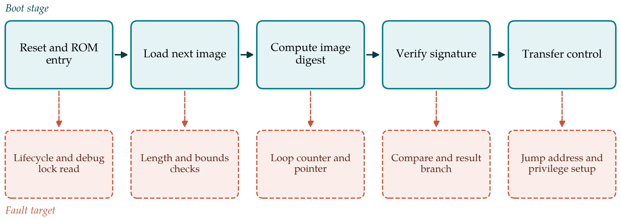
Figure 1 pairs the stages of a generic boot chain with the operations in each that a fault might usefully disturb. Locating those operations in time is the task of the fourth phase. Reading the image from flash produces visible bus activity, the digest computation has a regular power signature whose length scales with the image, and the signature verification follows it. The windows of interest are short: the comparison of the computed and expected values, the branch on its result, and the write that records the verdict. Where source or a disassembly of the boot code is available, the windows can be predicted by cycle counting and then confirmed against the traces.
4.4. Phase 5: The boot campaign
The campaign applies the characterised parameters to each candidate window with an unsigned or tampered image in place. The outcome classes are extended with the success criteria fixed in the first phase. Every attempt is logged with its parameters, since a single success needs to be reproducible to count. Results are reported per window as the number of successes among the attempts made, together with a confidence interval for the underlying rate. The score interval of Wilson (1927) behaves well for the small proportions typical of this work. A window with no success after many attempts supports only an upper bound on the success rate, and the report should say so in those terms.
4.5. Phase 6: Re-testing with countermeasures
Software hardening of boot code commonly includes repeating the verification, encoding the verdict in constants with a large Hamming distance in place of zero and one, checking that execution arrived by the expected path, and inserting random delays. Hardware adds glitch detectors and redundant logic. The final phase repeats the campaign with these measures enabled. Because duplicated checks can be defeated by two well-timed faults, the bench should support multiple glitches per boot. The comparison of success rates before and after hardening, under an unchanged injection set-up, is the main product of the evaluation.
5. Linking the Bench to Simulation
An open design allows the physical results to be explained and extended. At the instruction level, an emulator can replay the boot code while skipping or corrupting each instruction in turn, which lists every single fault that leads to a bypass under the assumed model and indicates where the bench should aim. At the register-transfer level the same exercise can be run on pipeline and control registers, which addresses the hidden-state effects that instruction-level models miss (Laurent et al., 2019). Agreement between the faults found physically and those the simulation predicts raises confidence in both. Disagreement is informative as well, since it shows the limits of the fault model in use.
6. Limitations and What Remains to Be Shown
The bench is a proposal and its usefulness is untested here. Several points would need to be established by applying it. Repeatability comes first: whether two laboratories following the procedure on the same target obtain comparable parameter maps and success rates. Transfer is a second question. A soft core on a gate array shares its logic design with the eventual chip and nothing of its physical layout, so results on one may say little about the other. Coverage is limited by the techniques included; laser injection, which the bench omits on grounds of cost, may reach faults the others do not. A negative result has limited meaning in any case, since the absence of a successful fault under a given budget of attempts and equipment is not evidence of immunity. Electromagnetic and high-voltage pulse equipment also brings electrical hazards that a laboratory must manage under its own safety rules.
7. Conclusion
Evaluating secure boot against fault injection requires modest equipment and a disciplined method more than it requires rare expertise. The bench proposed here assembles a prepared target, an affordable injector, a trigger path, observation channels and a logging controller, and the six-phase procedure moves from fault characterisation on known code to a measured campaign against the boot chain and its countermeasures. For RISC-V targets the availability of the design source allows physical results to be tied back to simulation, an opportunity that closed cores rarely afford. Whether the procedure yields consistent and transferable results is the question that experimental use must now answer.
Conflict of interest
To be declared by the author(s) before publication.
Funding
To be declared by the author(s) before publication.