1. Introduction
A small workshop that buys a collaborative arm usually programmes it by hand guiding. The operator leads the arm to each pose, stores it, and the arm returns there within its repeatability, which even for inexpensive arms is a small fraction of a millimetre. Trouble starts when poses come from elsewhere: from a CAD model, from a camera that locates parts, or from a programme copied from another robot. The arm is then asked for a pose in Cartesian space, and the error is governed by its absolute accuracy, which is commonly an order of magnitude worse than its repeatability. The international standard on robot performance treats the two as separate quantities for this reason (ISO, 1998).
Most of the gap is geometric. Link lengths, axis offsets and joint zero positions differ slightly from their nominal values, and the controller computes with the nominal ones. Kinematic calibration replaces them with identified values, and its methods have been settled for decades (Roth et al., 1987; Mooring et al., 1991). The obstacle for a small firm is the measuring equipment. Published calibrations of industrial arms typically rely on a laser tracker (Nubiola and Bonev, 2013), which is out of proportion to the price of a low cost arm.
This article proposes a procedure that replaces the tracker with a single camera and printed fiducial targets. The components are all established: planar camera calibration, fiducial detection, hand-eye calibration and least-squares identification. What is offered is their arrangement into a sequence that a technician can follow, with attention to the points where cheap equipment misleads. No application to a robot is reported.
2. Background
Robot calibration is conventionally divided into four tasks: modelling, measurement, identification and compensation (Roth et al., 1987). The proposal follows that division, and each task has a literature that constrains the choices available.
2.1. Kinematic models and their parameters
The standard description of a serial arm assigns four parameters to each link (Denavit and Hartenberg, 1955). It serves well for nominal kinematics but poorly for calibration when two consecutive joint axes are nearly parallel, because a small misalignment then produces a very large change in one parameter. Hayati and Mirmirani (1985) introduced an additional rotation about the y axis for such pairs, and this modification is routinely adopted. The point is of direct relevance here, since many six-axis collaborative arms have three consecutive parallel axes at the shoulder, elbow and first wrist joint. A model used for identification should be complete, continuous and free of redundant parameters (Mooring et al., 1991).
2.2. A camera as the measuring instrument
A calibrated camera that sees a pattern of known geometry can recover its own pose relative to the pattern. The intrinsic parameters and lens distortion are obtained from several views of a planar target (Zhang, 2000), and the pose from each later image by solving the perspective-n-point problem (Lepetit et al., 2009); the underlying geometry is set out by Hartley and Zisserman (2004). Square fiducial markers make the pattern self-identifying, so that each detected corner is matched to its known position without ambiguity even when only a fraction of the target is in view (Garrido-Jurado et al., 2014; Olson, 2011). Open implementations of all of these steps are available in the OpenCV library (Bradski, 2000).
The camera measures in its own frame, not the flange frame, and the fixed transform between the two is unknown. Finding it is the hand-eye problem, classically written as AX = XB and solved in closed form by Tsai and Lenz (1989), with later formulations on the Euclidean group (Park and Martin, 1994) and with dual quaternions (Daniilidis, 1999). These solutions assume that the robot poses are exact, which is precisely what is in doubt during calibration. They are therefore used here only for initial values.
3. The Proposed Procedure
Figure 1 shows the seven steps and the return path taken when validation fails. Before describing them, it helps to list the sources of error the procedure has to deal with. Table 1 does so and states how each is treated.
| Source of error | Effect | Treatment |
|---|---|---|
| Joint zero offsets | Pose error that varies across the workspace | Identified in Step 5 |
| Link length and axis misalignment | Smaller, configuration-dependent pose error | Identified in Step 5 with a Hayati term for parallel axes |
| Printer scaling | All measured distances scaled by a constant | Printed target measured with a steel rule in Step 1 |
| Target not flat | Biased marker poses | Target bonded to glass or metal plate |
| Camera intrinsics and focus | Systematic error, worst along the optical axis | Fixed focus and aperture; calibration in Step 2 |
| Hand-eye transform | Constant offset confused with robot error | Estimated jointly in Step 5 |
| Joint compliance and backlash | Load- and direction-dependent error | Not modelled; reduced by consistent approach direction |
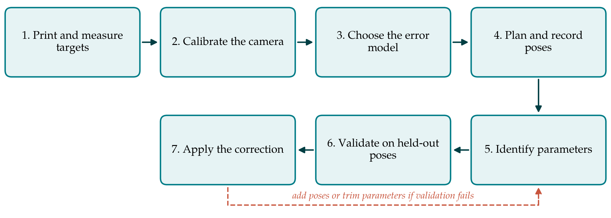
3.1. Step 1: Print, mount and measure the targets
A board of fiducial markers is printed on matt paper, matt because glossy stock produces specular highlights that disturb corner detection. Office printers do not reproduce dimensions exactly and may scale differently along and across the feed direction, so the printed board is measured in both directions with a steel rule or caliper and the measured pitch, not the nominal one, is entered in the software. The sheet is bonded without bubbles to a flat rigid backing such as float glass or a machined plate. Two or three boards placed at different heights and orientations in the workspace give better conditioning than one, and their relative positions need not be known in advance.
3.2. Step 2: Calibrate the camera
The camera is clamped to the flange with a bracket stiff enough that it does not shift during motion. Focus, aperture and zoom are set for the working distance and then locked mechanically; autofocus must be disabled, because any change of focus alters the intrinsic parameters. Intrinsics and distortion are estimated by the planar method from a few dozen views that tilt the target strongly and cover the whole image, including the corners. The reprojection residual should be inspected as a pattern across the image and not only as a single number, since a low average can conceal a poorly modelled lens edge.
3.3. Step 3: Choose the error model
The model takes the nominal parameters from the manufacturer and adds a small correction to each, with the Hayati term on the parallel-axis pairs. Not every correction can be identified. Some are indistinguishable from the unknown base and tool transforms, and others are nearly dependent for a given arm geometry. The practical test is to compute the identification Jacobian for the planned poses and examine its singular values; parameters associated with very small singular values are removed or fixed. On a first attempt it is prudent to identify only the joint zero offsets, which usually account for the larger part of the error, and to add link parameters only if validation shows a benefit.
3.4. Step 4: Plan and record the poses
Identification needs poses that excite every parameter, which means that each joint must move through a wide range while a target stays in view. The poses are generated in advance, checked for visibility and collisions in simulation, and split into an identification set and a validation set before any data are seen. At each pose the arm is allowed to settle, and the image is stored with the joint angles reported by the controller, not the commanded Cartesian pose. Approaching every pose from the same joint direction keeps backlash from appearing as random noise. Images in which markers are blurred, heavily foreshortened or fewer than a set minimum are discarded by rule.
3.5. Step 5: Identify the parameters
The unknowns are the kinematic corrections, the hand-eye transform and the pose of each board in the robot base frame. Initial values for the last two come from a closed-form hand-eye solution on the nominal kinematics. All unknowns are then refined together by minimising the reprojection error, the distance in pixels between each detected marker corner and its position predicted through the chain of base, arm, camera and board. Working in pixels weights each observation by what the camera actually measured and avoids treating the poorly observed depth direction as equal to the others. The minimisation is a standard nonlinear least-squares problem handled by the Levenberg-Marquardt method (Marquardt, 1963), preferably with a robust loss so that a few bad detections do not dominate.
3.6. Step 6: Validate on held-out poses
The identified model is judged only on the validation poses. For each, the board pose predicted from the joint angles is compared with the pose measured by the camera, before and after calibration, and the position and orientation errors are summarised. Residuals should also be plotted against each joint angle; a remaining trend indicates an unmodelled effect, and a model that fits the identification set well but the validation set badly has too many parameters. In either case the procedure returns to Step 3 or Step 4. An independent check with a different instrument, even a dial gauge against a reference block, is worth making because the camera cannot reveal its own bias.
3.7. Step 7: Apply the correction
Some controllers accept modified kinematic parameters directly. Where they do not, the correction is applied outside the controller: the desired Cartesian pose is passed through the inverse kinematics of the identified model, and the resulting joint angles are sent as a joint-space target (Siciliano et al., 2009). The identified values, the pose sets, the images and the software versions are archived so that the calibration can be repeated after a collision or a joint replacement.
4. Fitting the Procedure to a Small Workshop
The equipment list is short: a camera with a global shutter if one is affordable, a fixed-focus lens, a rigid bracket, printed boards on flat backing and a computer. The first calibration takes most of a day, largely spent on pose planning and scripting, and later repetitions take about as long as the robot needs to visit the poses. Lighting should be diffuse and constant. Temperature deserves a note in the record, because arms warm up in use and their geometry drifts with them; calibrating a cold arm that will work warm reproduces part of the error it was meant to remove.
Collaborative arms are designed to limit force and power in contact with people (ISO, 2016), and their light, compliant joints deflect under payload more than those of conventional industrial arms. A calibration performed with only the camera on the flange is valid for that load. If the working payload is substantially heavier, the poses should be recorded with a dummy mass of similar weight and centre of gravity.
5. Limitations and What Remains to Be Shown
The procedure is proposed, not demonstrated. Its accuracy is bounded by the camera, whose pose estimates are good across the image plane and weaker along the line of sight, and by the flatness and measured scale of the boards. It models geometry only, so elasticity, backlash, gear transmission error and thermal drift remain. Whether what is left is small enough for a given task is an empirical matter. The comparison that would settle it is a calibration of the same arm by this procedure and by a laser tracker, with both evaluated on a common set of tracker-measured poses. Repeating the camera-based calibration several times with fresh pose sets would show how stable the identified parameters are.
6. Conclusion
Absolute accuracy of low cost collaborative arms can in principle be improved with a camera, a printer and open software, using methods that are individually well established. The seven steps proposed here arrange those methods so that the commonest errors of cheap equipment, printer scaling, a changing focus, redundant parameters and unvalidated fits, are confronted in order. The procedure awaits comparison against a reference instrument, and until that is done its results on any particular arm should be confirmed by an independent measurement.
Conflict of interest
To be declared by the author(s) before publication.
Funding
To be declared by the author(s) before publication.