1. Introduction
The seismic design of retaining walls rests on an idea that predates most of soil dynamics. After the 1923 Kanto earthquake, Okabe (1926) and Mononobe and Matsuo (1929) extended Coulomb's sliding wedge by adding horizontal and vertical inertia forces to the weight of the wedge. The resulting expression, known as the Mononobe-Okabe or M-O equation, gives the total active thrust on a wall that yields enough to mobilise the full strength of a dry cohesionless backfill. It is compact, it needs only a friction angle and a seismic coefficient, and it has been written into codes across the world.
Cantilever walls of reinforced concrete are a different structure from the massive gravity walls for which the method was developed. Their stems bend, their bases rotate on the foundation soil, and a block of backfill resting on the heel moves with them. Engineers have also noticed for a long time that such walls perform better in earthquakes than the calculation suggests they should. Reports of flood-channel walls after the 1971 San Fernando earthquake (Clough and Fragaszy, 1977) and later reviews of field performance (Lew et al., 2010) found little damage to walls that had been given no explicit seismic design, provided the backfill and foundation did not liquefy.
This article reviews where the provisions of current codes diverge from what has been observed, and why. It is a narrative review of the published literature: classical analytical papers, experimental studies on centrifuges and shaking tables, numerical work, and the text of representative design documents. The intention is to help a designer see which parts of a code calculation are well founded, which are conservative by an uncertain margin, and which may in some conditions be unsafe.
2. The Classical Framework and Its Descendants
The M-O solution inherits every assumption of Coulomb's theory and adds several of its own. The backfill is taken as rigid-plastic, so acceleration is uniform through its height and there is no amplification or phase lag. The wall is assumed to move enough for an active wedge to form. The failure surface is planar. The equation says nothing about where the thrust acts; the original authors implied a hydrostatic distribution with the resultant at one third of the height (Kramer, 1996).
Seed and Whitman (1970) separated the total thrust into the static active component and a dynamic increment, proposed a linear approximation in which the increment of the pressure coefficient is about three quarters of the horizontal seismic coefficient, and recommended that the increment be applied at roughly six tenths of the wall height. The higher point of application came from shaking-table tests on small models at normal gravity, and it produced the inverted triangular distribution that many engineers still draw. In the same paper the authors remarked that walls designed for static loads with usual safety factors should resist moderate shaking without special provision, a comment that has been cited far less often than the formula.
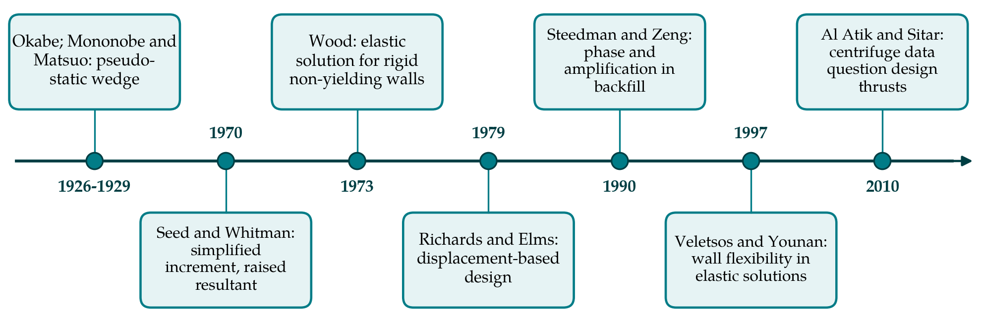
Two further developments completed the toolkit. Wood (1973) solved the elastic problem of a rigid wall on a rigid base retaining a uniform elastic soil, and obtained thrusts well above the M-O value, acting near mid-height. This became the reference for basement and other restrained walls. Richards and Elms (1979) took the opposite direction and treated a gravity wall as a sliding block in the sense of Newmark (1965), sizing it for a tolerable displacement and not for peak acceleration. Later analytical work addressed the limitations of the wedge itself. Steedman and Zeng (1990) introduced a finite shear wave velocity in the backfill, so that inertia forces vary in phase with depth. Koseki et al. (1998) modified the procedure for strong shaking, where the M-O expression gives implausibly flat failure planes or no solution at all. Figure 1 places these contributions in sequence.
3. What Codes Currently Require
Eurocode 8 Part 5 specifies a pseudo-static analysis with the M-O equation in an annex. The horizontal seismic coefficient is the design ground acceleration ratio multiplied by the soil factor and divided by a factor that depends on how much displacement the wall can accept: free gravity walls receive a substantial reduction, while walls restrained against movement, including braced and basement walls, receive none. For rigid restrained walls the annex gives an expression derived from Wood's solution, and the dynamic increment is to be applied at mid-height unless the wall is free to rotate about its toe (CEN, 2004).
In North American bridge practice the AASHTO specifications likewise adopt M-O, permit the seismic coefficient to be reduced for walls that can tolerate a few centimetres of sliding, and since the work reported in NCHRP Report 611 recognise height-dependent averaging of acceleration, the contribution of cohesion, and the generalised limit equilibrium method for cases where M-O breaks down (Anderson et al., 2008; AASHTO, 2012). The NEHRP provisions for buildings distinguish yielding from non-yielding walls and give a simplified thrust expression for each (BSSC, 2009). The three documents share a structure: choose a coefficient, compute a thrust from a wedge or an elastic solution, place it somewhere above the third point, and add it to the inertia of the wall.
4. Points of Divergence
Table 1 lists the main assumptions embedded in that structure and sets against each what experiments and field observation have reported. The subsections that follow take them in turn.
| Issue | Usual code assumption | What observations indicate | Sources |
|---|---|---|---|
| Size of increment | M-O thrust with a coefficient tied to peak ground acceleration | Measured increments often below M-O for stiff, dense backfill | Al Atik and Sitar, 2010; Mikola et al., 2016 |
| Point of application | Increment at 0.5 to 0.6 of wall height | Increment increases with depth; resultant near one third | Nakamura, 2006; Sitar et al., 2012 |
| Phasing | Peak thrust and peak wall inertia added directly | Peaks generally not simultaneous | Athanasopoulos-Zekko s et al., 2013 |
| Wall and base flexibility | Rigid wall, either fully yielding or fixed | Small flexibility or base rotation sharply lowers elastic thrust | Veletsos and Younan, 1997; Psarropoulos et al., 2005 |
| Cohesion | Ignored in the basic equation | Even modest cohesion reduces thrust markedly | Anderson et al., 2008 |
| Heel geometry | Thrust on a virtual vertical plane above the heel | Wedge above heel moves with wall; stem and stability loads differ | Kloukinas et al., 2015 |
4.1. Magnitude of the dynamic increment
Early centrifuge tests on a model cantilever wall by Ortiz et al. (1983) found total thrusts in broad agreement with M-O, though the moments did not agree as well. The more heavily instrumented experiments of Al Atik and Sitar (2010) on stiff and flexible U-shaped cantilever structures retaining dry medium-dense sand led to a sharper conclusion: for the conditions tested, the dynamic increment was smaller than the M-O estimate at all but low accelerations, and the traditional methods were judged conservative. Subsequent tests on basement-type and free-standing cantilever walls reached similar findings and suggested that no seismic increment need be added for well-drained cohesionless backfill below a moderate level of shaking, because static design factors of safety already cover it (Sitar et al., 2012; Mikola et al., 2016).
These results need careful reading. They apply to level, dry, dense backfill on a firm base, in models of walls of ordinary height. They also depend on how thrust is inferred, since pressure cells in sand are unreliable and the more trustworthy values come from strain gauges and load cells. Within those limits they are consistent with the field record summarised by Lew et al. (2010) and with Seed and Whitman's own remark.
4.2. Distribution and point of application
The inverted triangle has proved harder to defend than the magnitude. Centrifuge data consistently show the dynamic pressure increment growing with depth, so that the resultant lies close to one third of the height (Al Atik and Sitar, 2010). Nakamura (2006), working with gravity wall models, likewise found that the distribution and the mechanism in the backfill differed from the M-O picture. The elevated resultant in older shaking-table tests is now generally attributed to low confining stress in small models at normal gravity and to walls that rotated about the base. Because the bending moment at the base of a stem is proportional to the lever arm, moving the increment from six tenths to one third of the height changes the design moment far more than any plausible refinement of the coefficient. The consequence is easily seen when an existing wall is checked. A stem that appears overstressed under an inverted triangular increment will often be found adequate when the same thrust is distributed in proportion to depth, with no change to the seismic coefficient.
4.3. Phasing of thrust and inertia
Codes add the peak dynamic thrust to the peak inertia force of the wall as if the two occurred together. In a system where wall and soil have different natural periods they need not. Steedman and Zeng (1990) showed analytically that phase variation through the backfill alters both the magnitude and the position of the thrust. Centrifuge records indicate that the largest stem moment tends to coincide with the wall's own inertial loading, at an instant when the increment in earth pressure is at or near a minimum (Al Atik and Sitar, 2010). The numerical study of Athanasopoulos-Zekkos et al. (2013) examined this for yielding gravity-type walls and confirmed that the phase relation depends on wall mass, backfill stiffness and frequency content. A fixed rule cannot represent it, and simple summation errs on the conservative side for stiff walls.
4.4. Flexibility of the wall and its foundation
The gap between M-O and Wood's solution is large, and a cantilever wall sits somewhere between the two idealisations. Veletsos and Younan (1997) showed that allowing the wall to bend or its base to rotate reduces the elastic thrust substantially, and that for realistic flexibilities it approaches the M-O range. Psarropoulos et al. (2005) confirmed this with finite elements and extended it to inhomogeneous soil. A kinematic view, in which pressure arises from the difference between free-field displacement and wall displacement over the wall height, explains these trends and predicts that thrust depends on the ratio of wavelength to wall height and not on surface acceleration alone (Brandenberg et al., 2015). This is the most fundamental departure from code practice, since it removes the direct proportionality between peak ground acceleration and thrust on which the coefficient method depends.
4.5. Cohesion and the heel
Most compacted backfills and natural soils possess some cohesion, whether from fines, suction or cementation. The parametric charts in NCHRP Report 611 show that a small cohesion relative to the product of unit weight and wall height reduces the seismic active thrust considerably (Anderson et al., 2008). Codes that require it to be neglected are conservative in a way that may explain part of the good field record, although reliance on suction in a backfill that could become wet is a matter for judgement.
The heel raises a question the original theory never faced. For static design, the thrust is usually computed on a vertical plane through the back of the heel, a device valid when the heel is long enough for a Rankine zone to develop. Under shaking, the soil above the heel moves with the wall and contributes its inertia to sliding and overturning, while the stem is loaded by the stresses inside that block. Shaking-table tests and limit analysis by Kloukinas et al. (2015) showed that the critical instant for stability and the critical instant for stem bending differ, and that the governing failure mode depends on base geometry. A single thrust applied on a virtual back does not capture either check well.
5. Where Codes May Be Unconservative
It would be a misreading of this literature to conclude that seismic earth pressure can be ignored. The experiments that found low thrusts excluded the conditions under which walls have in fact failed. Saturated backfill that generates excess pore pressure imposes loads of a different order, and waterfront walls have suffered accordingly. Sloping backfill increases the thrust faster than level ground, and at high seismic coefficients the wedge solution degenerates (Koseki et al., 1998). Soft or loose foundation soil allows rotation that the pressure calculation does not address. Tall walls, and walls whose height is a significant fraction of the shear wavelength in the backfill, lie outside the range of the centrifuge data and may be subject to amplification effects (Brandenberg et al., 2015). Walls behind which a perched water table can form after heavy rain deserve the same caution, since the drainage assumed in design is not always maintained in service. In each of these cases a code calculation based on a reduced coefficient and a level dry backfill could understate the demand.
6. Gaps and Future Work
Several questions remain open. Experimental data are concentrated on dry sand, level backfill and prototype heights of a few metres, so the behaviour of tall cantilever and counterfort walls, of cohesive and partially saturated fills, and of walls on compliant foundations is known mainly from numerical models that have not been validated against measurements in those conditions. Instrumented full-scale walls that have recorded an earthquake are rare. The kinematic framework is promising but has yet to be turned into a design procedure that also handles yielding and base sliding. Finally, the calibration of displacement-based reductions for cantilever walls, as distinct from gravity blocks, has received little attention, although the heel and the foundation rotation make the sliding-block analogy an imperfect one. Instrumentation of new walls in seismically active regions, with strain gauges on the stem and accelerometers in the backfill, would in time supply what model tests cannot.
7. Conclusion
For a cantilever wall retaining level, drained, cohesionless or lightly cohesive backfill on firm ground, the weight of experimental and field evidence is that current code calculations overstate the seismic thrust, place it too high on the stem and combine it too severely with wall inertia. The conservatism is not uniform and cannot be relied on as a margin elsewhere. Where backfill is saturated, or sloping, or where the wall is tall or stands on soft ground, the same simplifications lose their basis. Codes have begun to respond by admitting cohesion, height effects and displacement tolerance. The step still to be taken is to replace a single coefficient with a description of the wall and backfill as an interacting system.
Conflict of interest
To be declared by the author(s) before publication.
Funding
To be declared by the author(s) before publication.