1. Introduction
A bridge pier and its foundation respond to an earthquake as one system. Flexibility of the foundation lengthens the period of the structure, changes the distribution of displacement demand between the pier and the ground, and adds damping through radiation and soil hysteresis. Whether these effects reduce or increase the demand on the pier depends on the structure and on the motion, and the common assumption that ignoring them is safe does not always hold (Mylonakis and Gazetas, 2000). For an existing bridge, where the question is how much capacity remains and where it will be exhausted first, a reasonable account of foundation behaviour is part of the assessment and not a refinement of it.
The tools on offer sit at two extremes. Design texts and codes describe equivalent linear springs at the base of the pier, with stiffness taken from elastic solutions or from a pushover of the pile group (Priestley et al., 1996; CEN, 2005). At the other end, the full pile group can be modelled as beams supported on nonlinear soil springs along their length, driven by the free-field motion at each depth. The first approach cannot represent yielding of the soil or the coupling between lateral force and moment at large displacement. The second can, but its cost in modelling effort and in parameters is hard to justify across a stock of ordinary bridges.
This article proposes a simplified procedure based on a macro-element placed at the pile head. The aim is a foundation model that an assessor can set up from routine site investigation data, that behaves nonlinearly in a physically reasoned way, and that adds only one element per foundation to the structural model. The procedure is assembled from published work. It is presented as a proposal and has not been validated here; no analysis results are reported.
2. Background
The procedure draws on three lines of earlier research, summarised in turn.
2.1. Linear impedance and kinematic interaction
The classical treatment of soil-structure interaction separates the problem into a kinematic part and an inertial part (Wolf, 1985). In the kinematic part, a massless foundation is subjected to the incoming waves and its motion, which differs from the free-field motion because the piles resist the deformation of the soil, becomes the input to the structure. In the inertial part, the structure is supported on frequency-dependent springs and dashpots, the impedance functions, that represent the stiffness of the foundation and the energy it radiates. Impedances for single piles were derived by Novak (1974) and are available as simple expressions for common soil profiles (Gazetas, 1991). Group effects arise from waves emitted by one pile reaching its neighbours and can be handled with interaction factors (Dobry and Gazetas, 1988). The kinematic response of piles and groups was characterised by Fan et al. (1991).
2.2. Nonlinear Winkler models
Nonlinearity near the pile is conventionally described by lateral load-transfer curves, the p-y curves developed from field loading tests in soft clay (Matlock, 1970) and sand (Reese et al., 1974) and adopted in offshore practice (API, 2000). For seismic loading the curves are attached to the free-field soil column, with dashpots to represent radiation, and the model is driven by the displacement history at each depth. Boulanger et al. (1999) evaluated this approach against centrifuge tests and found that it reproduced the main features of the measured response. It remains the reference against which a simpler model should be judged.
2.3. Macro-elements
A macro-element replaces the foundation and the soil mobilised by it with a constitutive law written directly in terms of the resultant forces and the corresponding displacements at a reference point. The idea was introduced for strip footings on sand by Nova and Montrasio (1991), who borrowed the structure of hardening plasticity: a surface in force space bounding the admissible loads, a flow rule and a hardening law. Cremer et al. (2001) extended it to cyclic loading with uplift, and later formulations simplified the ingredients for dynamic analysis (Chatzigogos et al., 2009). For piles, the yield surface relates horizontal force and moment at the head, and couples them much more strongly than for a footing because lateral resistance comes from bending of the pile against the soil. A pile-head macro-element for bridge monoshafts was presented by Correia et al. (2012), and Li et al. (2016) developed a hypoplastic version for single piles in sand under three-dimensional loading.
3. Anatomy of the Simplified Element
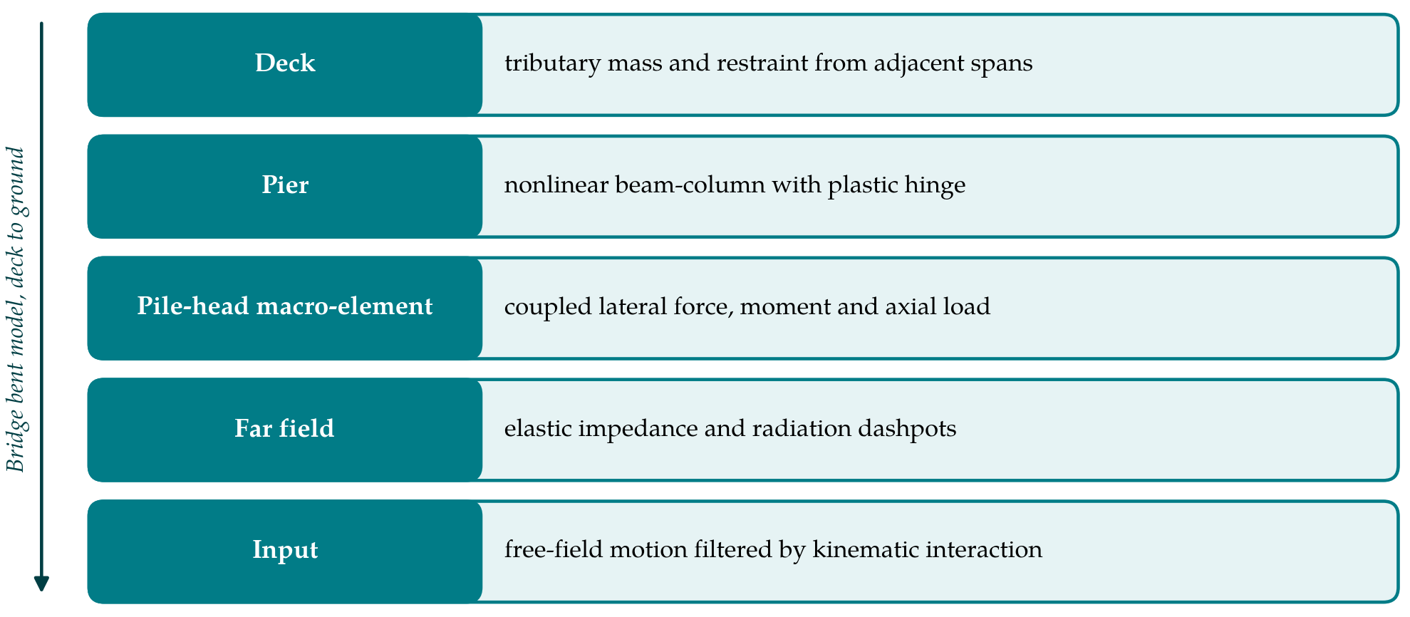
The element proposed for assessment use has the minimum set of parts needed to capture stiffness, capacity, hysteresis and radiation. Table 1 lists them, with the physical feature each represents and the published source from which it can be calibrated. Figure 1 shows where the element sits in a model of a bridge bent.
| Component | What it represents | Basis for calibration |
|---|---|---|
| Elastic stiffness matrix | Coupled lateral, rocking and vertical stiffness at small strain | Closed-form pile impedances (Gazetas, 1991) |
| Group interaction | Softening of each pile by waves from its neighbours | Interaction factors (Dobry and Gazetas, 1988) |
| Failure surface | Combinations of head force and moment at ultimate capacity | Limit analysis of pile and soil (Broms, 1964) |
| Hardening rule | Gradual loss of stiffness between elastic range and failure | Monotonic pushover with p-y curves (API, 2000) |
| Unload-reload rule | Hysteretic damping and residual displacement | Cyclic macro-element formulations (Correia et al., 2012) |
| Radiation dashpots | Energy carried away by outgoing waves | Damping terms of the impedance functions (Novak, 1974) |
| Input motion filter | Difference between free-field and pile-head motion | Kinematic interaction factors (Fan et al., 1991) |
4. The Procedure
The procedure is set out as six steps. They are written for a single pier on a pile group or a monoshaft and are repeated for each foundation that differs in geometry or ground conditions.
4.1. Step 1: Characterise the ground and the piles
The assessor assembles a soil profile with small-strain shear modulus and strength for each layer, the groundwater level, and the as-built pile details: diameter, length, spacing, reinforcement and the connection to the cap. For older bridges the last of these is often the least certain and the most consequential, since a pinned or weakly reinforced connection changes the head fixity on which both stiffness and capacity depend. Where liquefaction or lateral spreading is possible the procedure does not apply in its present form, and a different class of analysis is required.
4.2. Step 2: Compute the elastic stiffness and damping
The small-strain stiffness matrix of a single pile is obtained from closed-form expressions for the appropriate idealised profile, with the off-diagonal term that couples translation and rotation retained. Group stiffness is then built using dynamic interaction factors evaluated at the fundamental frequency of the bridge. Radiation damping coefficients are taken from the same sources. Below the fundamental frequency of the soil deposit little energy is radiated, and the dashpots are reduced or removed in that range (Gazetas, 1991).
4.3. Step 3: Establish the failure surface
Ultimate combinations of horizontal force and moment at the pile head are found from a mechanism analysis in the manner of Broms (1964), considering both failure of the soil along a short pile and formation of plastic hinges in a long one. Several ratios of moment to force are analysed and a smooth surface is fitted through the resulting points. For a group, axial capacities of the outer piles enter through the push-pull couple that resists overturning, so the vertical load becomes a third axis of the surface.
4.4. Step 4: Calibrate the hardening and cyclic rules
The transition from elastic response to failure is calibrated against a monotonic pushover of the pile or group on conventional p-y springs, run once for each foundation type. The macro-element hardening parameters are adjusted until its force-displacement and moment-rotation curves follow those of the pushover along two or three load paths. For unloading and reloading, the simplest defensible choice is a kinematic rule that reproduces the monotonic curve on first loading and gives closed loops thereafter. Gapping between pile and cohesive soil, which pinches the loops, can be represented by an additional parameter if the soil conditions suggest it.
4.5. Step 5: Define the input motion and run the analysis
Free-field motion at the surface is modified by kinematic interaction factors to give the foundation input motion. For slender piles in uniform soil and the frequencies that matter for most bridges the modification is small, and the free-field motion is commonly accepted in such cases; for large-diameter shafts and layered profiles with sharp stiffness contrasts it should be evaluated. The macro-element is inserted between the base of the pier and the node at which the input motion is applied, with the radiation dashpots in parallel with its elastic part so that they are not credited with damping once the near field has yielded. Nonlinear response history analysis is then carried out in the usual way.
4.6. Step 6: Interpret foundation demands
The analysis returns histories of force, moment, displacement and rotation at the pile head. These are compared with acceptance limits for the foundation, and the peak head actions are applied to the pushover model of Step 4 to recover the bending moment distribution down the piles. Residual displacement and rotation of the element give a first estimate of permanent foundation movement, which for many bridges governs serviceability after the event.
5. Fitting the Procedure to Assessment Practice
Most of the effort lies in Steps 3 and 4, and it is spent once for each foundation type and not for each analysis. An authority with many bridges of similar construction could tabulate element parameters against pile size and soil class. The element itself requires a plasticity-based zero-length formulation with coupled degrees of freedom; where the assessor's software lacks one, uncoupled nonlinear springs can be calibrated to the same pushover curves, at the price of losing the interaction between force and moment that distinguishes a pile from a footing.
6. Limitations and What Remains to Be Shown
The procedure has been reasoned from the literature and not tested. Before it is relied on, its predictions should be compared with those of a full beam-on-nonlinear-Winkler model for a range of bridges, soils and motions, and with the centrifuge data sets that have been used to evaluate such models. The comparison should cover peak pier drift, pile-head actions and residual displacement, and should establish the conditions under which the simplified element departs unacceptably from the reference.
Some limitations are already clear. The element lumps all nonlinearity at the pile head and so cannot represent a plastic hinge forming at depth as a separate event. Frequency dependence of the impedance is reduced to a single value. Kinematic bending of piles at layer interfaces is not computed and must be checked separately. Soils that lose strength during shaking are outside its scope. None of these is unusual for a simplified method, but each marks a boundary that users should respect.
7. Conclusion
A pile-head macro-element allows the nonlinear behaviour of a piled bridge foundation to be included in a seismic assessment at little more cost than a linear spring. The six-step procedure proposed here builds the element from closed-form impedances, a mechanism-based failure surface and a single pushover calibration, all of which use data that a competent investigation of an existing bridge would provide. Its accuracy relative to more detailed models has yet to be demonstrated, and that demonstration is the necessary next step.
Conflict of interest
To be declared by the author(s) before publication.
Funding
To be declared by the author(s) before publication.