1. Introduction
Rings, rollers and shafts made from high-carbon chromium bearing steel are hardened before they are finished, and for most of the last century finishing meant grinding. The arrival of tool materials able to cut steel above about 45 HRC changed that. Single-point turning of the hardened part can produce the required geometry in one setup, with a flexible tool path and without the coolant and swarf treatment that grinding demands (König et al., 1984; Tönshoff et al., 2000). The process is normally run dry, partly because the heat generated in the shear zone softens the work material ahead of the edge and partly because removing the fluid removes a cost and a waste stream (Klocke and Eisenblätter, 1997).
Polycrystalline cubic boron nitride and alumina-based ceramics are the tool materials most often associated with hard turning, and most of the research on wear concerns them (Huang et al., 2007; Dogra et al., 2010). Both are expensive, and both are brittle enough to make interrupted cuts and less rigid machines a risk. Coated cemented carbide is cheaper by a wide margin, tougher, and available in every insert geometry. Whether it can do useful work on bearing steel at 58 to 62 HRC depends on how fast it wears and on how predictable that wear is.
This article reviews the published evidence on that question. It concentrates on the progression of wear with cutting time, because the shape of the wear curve, and not only the tool life it ends in, decides whether a process can be planned and trusted in production.
2. Scope and Approach
The review is narrative. It draws on standard texts on metal cutting, on the survey papers that have organised the hard turning literature, and on experimental reports that are widely cited for coated carbide tools. Studies on AISI 52100 are discussed alongside work on hardened AISI 4340 and on cold work tool steels, since much of the coated carbide evidence comes from those grades and the mechanisms carry over. No count of sources is claimed and no pooled estimate is attempted, because test conditions, hardness levels and wear criteria differ too much between reports for their numbers to be combined.
3. Hard Turning and the Place of Coated Carbide
Cutting hardened steel differs from conventional turning in ways that matter for the tool. Depths of cut and feeds are small, so the chip forms on the nose radius and on the edge chamfer or hone, and the effective rake angle is strongly negative. The specific cutting energy is high and concentrated in a narrow contact. The chip is usually segmented, with adiabatic shear bands that load the edge cyclically (Tönshoff et al., 2000). The radial force component, small in ordinary turning, becomes the largest of the three and is the one most sensitive to flank wear (Bartarya and Choudhury, 2012).
Cemented carbide loses hardness as temperature rises, far more quickly than cubic boron nitride or alumina does (Trent and Wright, 2000). A carbide edge therefore cannot be run at the speeds used with those materials, and the practical question is whether a coating can protect the substrate well enough at lower speeds to give an economic tool life. The comparative tests are consistent on the ranking. Aslan (2005), cutting a cold work tool steel at 62 HRC, found that coated carbide and cermet grades were outlasted by mixed ceramic and cubic boron nitride tools. Reviews that weigh tool cost against tool life nonetheless treat coated carbide as a legitimate choice at the lower end of the hardness range and at moderate speeds (Chinchanikar and Choudhury, 2015).
4. Forms and Mechanisms of Wear
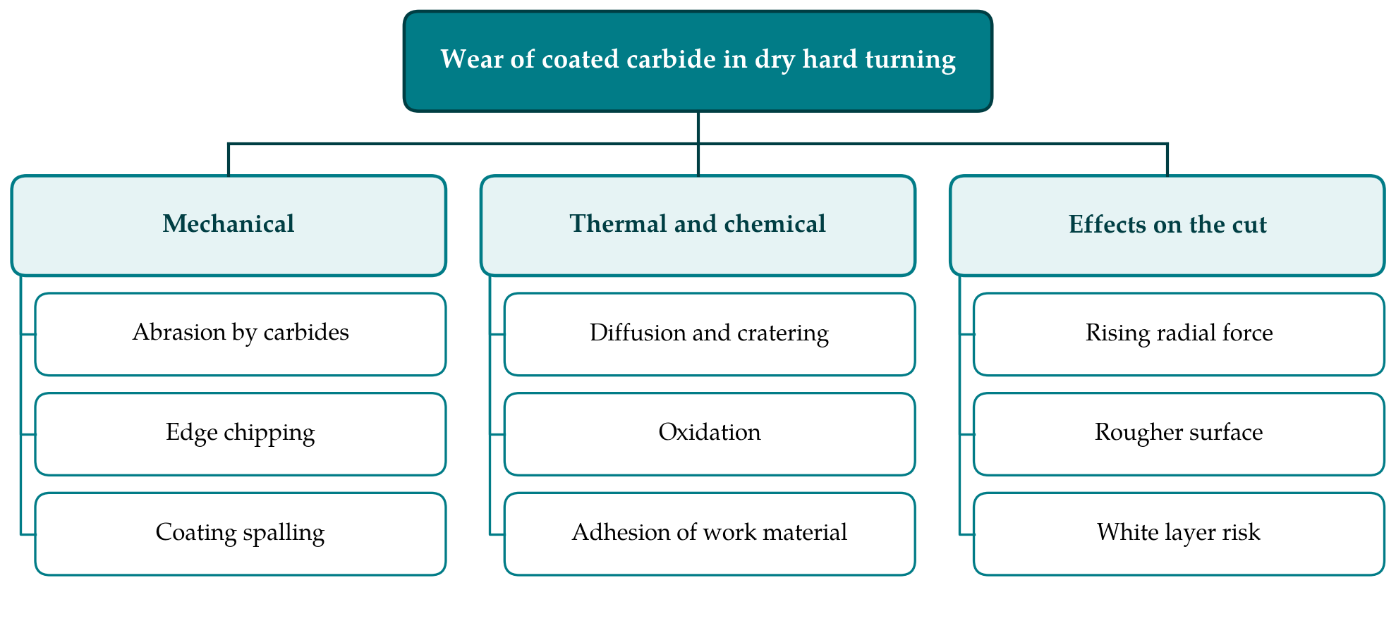
The wear seen on coated carbide after hard turning takes the same forms that ISO 3685 defines for single-point tools: a wear land on the flank, a crater on the rake face, notching at the depth-of-cut line, and chipping or fracture of the edge (ISO, 1993). What differs is their relative weight and the mechanisms behind them. Figure 1 groups the mechanisms reported in the literature and the effects that follow from them.
4.1. Flank wear and abrasion
Flank wear is the form that limits tool life in almost every report. Hardened bearing steel consists of tempered martensite carrying a dispersion of hard chromium-rich carbides, and these particles plough the flank as the freshly cut surface slides past it. Work with cubic boron nitride tools on hardened bearing steel identified abrasion by these carbide particles as the main cause of wear (Poulachon et al., 2001), and the same abrasive action is identified as the principal mechanism for multilayer coated carbide on hardened AISI 4340 (Suresh et al., 2012). While the coating remains intact on the flank the wear land grows slowly. Once it is worn through, the softer substrate is exposed and the rate rises.
4.2. Crater wear and thermally driven mechanisms
On the rake face the chip slides over the tool at high temperature and under high normal stress. Diffusion of tool constituents into the chip, and chemical reaction between the two, deepen a crater behind the edge (Trent and Wright, 2000; Shaw, 2005). An alumina layer in the coating is an effective barrier to this while it lasts. In dry cutting the hot tool surface outside the contact is also exposed to air, and oxidation contributes to notch wear at the edges of the contact zone. Adhesion of work material to the tool, followed by plucking of coating fragments when the adhered layer breaks away, is reported at the lower speeds where carbide tools are usually run.
4.3. Coating failure and chipping
A coating can fail before it wears out. Spalling and delamination expose the substrate locally and are favoured by the cyclic load of segmented chip formation and by thermal cycling in interrupted cuts. The review of coated tools by Bouzakis et al. (2012) relates such failures to film adhesion, residual stress and the fatigue strength of the coating, and shows how much they depend on edge preparation before deposition. Micro-chipping of the edge is common early in the life of a sharp insert and is one reason why a chamfer or hone is specified for hard turning.
5. How Wear Develops Over Cutting Time
Plotted against cutting time, the width of the flank wear land follows the pattern familiar from conventional turning. An initial period of rapid wear, as the sharp edge beds in, gives way to a longer period in which the land grows at a nearly constant rate, and this ends in a third stage in which wear accelerates until the edge fails (Shaw, 2005). The pattern is described in the hard turning reports for coated carbide as well, with one qualification: the steady stage lasts as long as the coating does on the flank, so the transition to rapid wear is tied to coating breakthrough and can be abrupt.
Tool life is the cutting time at which a chosen criterion is reached. ISO 3685 recommends an average flank wear land of 0.3 mm when wear is regular (ISO, 1993). Many hard turning studies adopt a smaller value, on the reasoning that a finishing cut is ended by loss of surface quality or dimensional accuracy before the tool is worn out in the conventional sense. Since reports differ in the criterion they use, their tool lives are not directly comparable, and a reader should check the criterion before comparing any two results.
The relation between cutting speed and tool life established by Taylor (1907) holds in form for coated carbide on hardened steel: tool life falls as a power of speed, and steeply. Extended versions add feed and depth of cut with smaller exponents. The exponent for speed reported for carbide on hardened steel is such that a modest increase in speed removes a large part of the tool life, which is the quantitative expression of the thermal limit described above.
6. Influence of Cutting Conditions and Workpiece Hardness
Experimental studies that vary speed, feed and depth of cut in a designed plan agree that cutting speed has the largest effect on flank wear and tool life, feed a smaller one, and depth of cut the least (Chinchanikar and Choudhury, 2013; Suresh et al., 2012). The usual explanation is that speed controls the temperature of the edge, and temperature controls both the softening of the substrate and the rate of the thermally activated mechanisms. Feed has its main influence on surface roughness, through the geometry of the feed marks left by the nose radius.
Workpiece hardness acts in two directions. A harder workpiece raises the stress on the edge and the abrasive severity of the carbides, and tool life shortens as hardness increases (Chinchanikar and Choudhury, 2013). At the same time, hardness changes the mechanics of chip formation, and the work of Matsumoto et al. (1986) on AISI 4340 showed that it also changes the residual stress left in the surface. Much of the coated carbide evidence was gathered below the hardness at which bearing rings are finished, so extrapolation to fully hardened AISI 52100 should be made with caution.
Running dry is the normal condition in these tests and is part of the case for hard turning (Klocke and Eisenblätter, 1997). It leaves the tool without external cooling, which for cubic boron nitride is acceptable and for carbide is a constraint. It also removes the thermal shock that intermittent wetting of a hot edge can cause, which is one reason dry cutting is often preferred with brittle coatings.
7. Coating Architecture and Edge Preparation
Coatings for carbide tools have developed from single layers of titanium nitride or carbide to multilayer and nanostructured systems in which each layer has a distinct task (Prengel et al., 1998). Table 1 summarises the families used in hard turning studies. In the thick films made by chemical vapour deposition, a titanium carbonitride layer supplies abrasion resistance, an alumina layer supplies chemical stability and thermal insulation, and a thin titanium nitride top layer makes wear easy to see. Physical vapour deposition gives thinner films in compressive stress on a sharper edge, and titanium aluminium nitride is its best known product. Its resistance to oxidation is attributed to a dense alumina film that forms on the surface at cutting temperature (PalDey and Deevi, 2003).
| Coating | Usual deposition route | Contribution to wear resistance | Main limitation |
|---|---|---|---|
| TiN | Chemical or physical vapour deposition | Low friction against steel; visible wear indicator | Oxidises at moderate cutting temperature |
| TiCN | Chemical vapour deposition, often at medium temperature | High hardness and abrasion resistance on the flank | Less chemically stable than alumina on the rake face |
| Al O 2 3 | Chemical vapour deposition | Chemical inertness and thermal insulation of the substrate | Brittle; needs a bonding layer beneath it |
| TiAlN and AlTiN | Physical vapour deposition | Hot hardness; protective oxide film forms in the cut | Thin film, quickly consumed by abrasion |
| Multilayer TiCN/Al O /TiN 2 3 | Chemical vapour deposition | Combines flank and rake protection in one insert | Thick film blunts the edge and can spall |
Direct comparisons support the multilayer systems. Sahoo and Sahoo (2012) turned hardened AISI 4340 with uncoated and multilayer coated inserts and reported that the uncoated carbide failed early while the coated grades gave a usable tool life with flank wear growing steadily. The result is typical of the literature: uncoated carbide has no place in this application, and among coated grades those with an alumina layer are favoured as speed rises.
Edge geometry interacts with the coating. A chamfered or honed edge resists chipping and supports the coating, at the price of higher forces and more heat. Wiper geometries allow a higher feed for a given roughness, which shortens the time the edge spends in the cut for each part. These choices are discussed at length for cubic boron nitride tools (Dogra et al., 2010) and much less for carbide, where the edge condition supplied by the manufacturer is usually accepted as it comes.
8. Consequences of Wear for the Machined Surface
A bearing surface is judged by more than its roughness. Rolling contact fatigue life depends on the residual stress and microstructure of the layer just beneath the surface, and a worn tool changes both. As the flank wear land widens, rubbing between tool and workpiece raises the surface temperature, and a rehardened white layer can form over a softer, overtempered zone. Chou and Evans (1999) linked white layer thickness on hard turned AISI 52100 to flank wear and cutting speed, and Guo and Sahni (2004) showed that turned and ground white layers differ in structure and properties. Residual stress tends to shift from compressive towards tensile at the surface as wear grows (Tönshoff et al., 2000).
These findings come mainly from cubic boron nitride tools. The mechanism is thermal and geometric, so there is every reason to expect it with carbide, and perhaps sooner, since a carbide edge runs with a larger wear land for more of its life. The comparison of hard cutting and grinding by Klocke et al. (2005) makes the general point that process capability in hard turning is bounded by tool wear. For coated carbide this implies that the wear criterion should be set by surface integrity and not by the insert's ability to go on cutting.
9. Modelling and Monitoring
Two kinds of model appear in the literature. Mechanistic wear rate equations relate the loss of tool material to contact stress, sliding velocity and interface temperature; that of Usui et al. (1984) remains the standard form and is used inside finite element simulations of cutting. Empirical models fit flank wear or tool life to the cutting parameters by regression or response surface methods, or by neural networks as in the work of Özel and Karpat (2005). Empirical models describe the tested range well and say little outside it. Neither kind yet represents coating breakthrough explicitly, which is the event that ends the steady stage for a coated insert. The sensitivity of the radial force to flank wear, noted earlier, makes it the most promising signal for monitoring wear during the cut.
10. Gaps and Future Work
Four gaps stand out. The first is material coverage: systematic wear curves for coated carbide on through-hardened AISI 52100 at bearing hardness are scarce compared with those for AISI 4340 and tool steels. The second is repeatability. Tool life is a scattered quantity, and many reports rest on a single edge per condition, so the reliability of a predicted life is unknown. The third is reporting. Without a common wear criterion, a stated coating composition and thickness, and a stated edge preparation, results cannot be compared or reproduced. The fourth is the link to function: few studies of coated carbide follow wear through to white layer formation, residual stress and fatigue performance of the part.
Economic comparison is a further open matter. Coated carbide is attractive only if its cost per finished part, including tool changes and the risk of scrapping a hardened ring, is lower than that of cubic boron nitride. That calculation depends on wear data of the kind described above and should be made for realistic batch sizes and machine rates before any general recommendation is offered.
11. Conclusion
The literature gives a coherent account of how coated carbide wears in dry turning of hardened steel. Flank wear by abrasion dominates, it develops in three stages, and the steady stage lasts until the coating is breached. Cutting speed is the strongest influence because it sets edge temperature, and multilayer coatings with an alumina layer extend the usable range. Within a moderate speed range the tool is predictable and inexpensive. The account is weakest where bearing manufacture most needs it: at full hardness, with statistical confidence, and with the condition of the machined surface as the measure of when an edge is spent.
Conflict of interest
To be declared by the author(s) before publication.
Funding
To be declared by the author(s) before publication.