1. Introduction
An injection moulding machine earns money only while the mould is closed on a shot of good parts. A custom moulder with a few machines may change moulds on each of them several times a week, and each change costs more than the time on the clock: the machine is idle, the setter is occupied, material is purged to waste, and the first parts are scrapped until the process settles. The usual defence is to run larger batches, which turns the lost time into stock and into longer waits for customers. Ohno (1988) described this trade as the root of overproduction, and the Toyota answer was to attack the changeover itself.
The method that resulted is the single-minute exchange of die of Shingo (1985), called quick die exchange or quick mould change on the moulding shop floor. It is among the best documented of lean techniques, and it features in general accounts of lean production (Womack and Jones, 1996). Its reputation rests largely on press shops in large firms. A small moulder faces a different situation: machines from several makers and decades, moulds owned by customers, a single overhead crane, and a setter who is also the process technician.
This article proposes an implementation procedure for that setting. It is a methodological proposal built from the published literature on changeover improvement and from general knowledge of the moulding process. It reports no application, and no times, savings or plant data are presented. The aim is to give a small plant a sequence of work that it can follow and test for itself.
2. Background
Two bodies of knowledge inform the procedure: the changeover methodology and its critics, and the particular anatomy of a mould change.
2.1. Shingo's methodology and its reinterpretation
Shingo distinguished internal setup, work that can be done only when the machine is stopped, from external setup, work that can be done while it runs. His conceptual stages follow from the distinction: observe a changeover in which the two are mixed, separate them, convert internal work to external, and streamline all operations (Shingo, 1985). Later practitioners extended the toolkit with waste-elimination routines for the setup crew (Sekine and Arai, 1992).
A group at the University of Bath examined the methodology critically over several years. Their central points are three. Changeover does not end when the new tool is fitted but when the line reaches full output at acceptable quality, so the run-up period belongs to the problem (McIntosh et al., 2000). Improvement can come from rearranging tasks, which is what the separation of internal and external work achieves, or from altering tasks so that they take less time, and Shingo's stages give too little weight to the second (McIntosh et al., 2007). And much of the second kind depends on the design of equipment and tooling, so organisation-led and design-led improvement should be weighed against each other from the start (Mileham et al., 1999; McIntosh et al., 2001). Design rules for changeover-capable equipment have been set out by Van Goubergen and Van Landeghem (2002).
Published applications show that the method must be fitted to the process. Tailored versions have been described for welding cells (Ferradás and Salonitis, 2013) and for automotive component production (Cakmakci, 2009), and Moxham and Greatbanks (2001) argue from a textile plant that teamwork, visual control and performance measurement are prerequisites without which the technique does not take hold.
2.2. Anatomy of a mould change
A mould change on a horizontal machine involves more than swapping steel. The outgoing mould is drained or blown clear of coolant, its hoses, hot-runner cables and ejector coupling are disconnected, the clamps are released and it is lifted out by crane. The incoming mould is lowered between the tie bars, located on the fixed platen, clamped, and reconnected. If the material or colour changes, the barrel is purged and its temperature profile reset, and hygroscopic resins such as polyamide and polycarbonate must already have been dried. The mould is brought to temperature, process settings are entered, and shots are made until parts pass inspection (Rosato et al., 2000). In the vocabulary of total productive maintenance the whole interval counts as setup and adjustment loss, one of the six big losses that reduce equipment effectiveness (Nakajima, 1988).
3. The Proposed Procedure
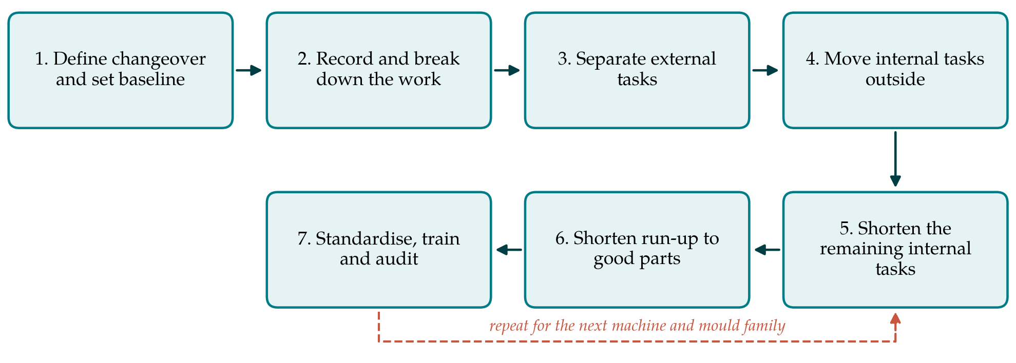
The procedure has seven steps, shown in Figure 1. It is applied to one machine and one family of moulds at a time, and the loop in the figure indicates that the work is then repeated elsewhere with what has been learned.
3.1. Step 1: Define the changeover and set a baseline
The plant first agrees what is being measured. Following McIntosh et al. (2000), the proposed definition is the elapsed time from the last good part of the outgoing job to the first part of the incoming job that is produced at the planned cycle time and passes inspection. The definition deliberately includes heating, purging and trial shots. A baseline is taken from several ordinary changeovers on the chosen machine, recorded without special preparation, together with the material scrapped during each. A target is set, but it is expressed as a direction and a review date and not as a promise of single minutes.
3.2. Step 2: Record and break down the work
One complete changeover is filmed with the setter's agreement, and the film is reviewed by the people who do the work. Each element is listed with its duration, who performed it, what tools and aids were used, and where the setter walked. Waiting is recorded as carefully as work: waiting for the crane, for a fitting, for the dryer, for the mould to heat, for quality approval. The output is an element sheet in which each line is marked as internal or external as currently performed.
3.3. Step 3: Separate external tasks
The cheapest gains come from doing before the stop what does not need the machine. The incoming mould is inspected, fitted with its lifting eye and brought to the machine on a trolley. Hoses, clamps, tools and the setting sheet are laid out on a dedicated cart. Resin is in the dryer early enough to be ready. The crane is booked. After the restart, the outgoing mould is cleaned, protected and returned to its place while the machine runs. A checklist is the main instrument at this step, and a current-state map of the kind described by Rother and Shook (1999) helps to show planners how changeover time governs batch size.
3.4. Step 4: Move internal tasks outside
Some tasks are internal only because of how the equipment is arranged. Mould heating is the leading case: a mould that is brought to temperature on a preheating station, or connected to a temperature controller before it is hung, removes a long wait from the stopped period. Hoses can be assembled into manifolds off line so that one connection replaces many. Process settings can be stored as recipes and loaded instead of typed. Table 1 lists the main elements of a mould change with the organisational and the design measure that applies to each.
| Element | Organisational measure | Design measure |
|---|---|---|
| Fetching mould, tools and material | Pre-stage on a trolley and cart; checklist before the stop | Fixed storage locations close to the machines |
| Lifting out and in | Book the crane; two people work in parallel | Standard lifting points; balanced lift |
| Locating and clamping | Sorted, dedicated clamps and one tool size | Uniform back plates and locating rings; hydraulic or magnetic clamping |
| Cooling and hot-runner connection | Colour-coded hoses; drain or blow out circuits | Manifolds with quick or multi-couplers; standard connector layout |
| Ejector coupling | Check coupling type before the stop | One coupling standard across moulds |
| Mould and barrel heating | Start heating early; schedule similar jobs together | Preheating station; insulated platens |
| Purging and material change | Sequence colours from light to dark; material ready and dry | Dryer and loader at each machine |
| Setting and first-off approval | Stored recipes; agreed approval criteria and limit samples | Cavity pressure or other in-mould sensing |
3.5. Step 5: Shorten the remaining internal tasks
What must be done at the stopped machine is then made quicker. Parallel working, with a second person on the non-operator side, removes much of the walking around the machine. Bolts of one size, slotted clamps and a single wrench reduce handling. Adjustment is treated as avoidable: if every mould in a family has the same back-plate dimensions and locating ring, the machine needs no change of mould height or ejector stroke between them. Here the choice between organisation and design becomes explicit. Quick-clamping systems and multi-couplers cost money per mould as well as per machine, and a small plant should cost them against the changeover frequency of the specific machine before buying (McIntosh et al., 2001).
3.6. Step 6: Shorten the run-up to good parts
In moulding the run-up is often the longest part of the changeover and the least visible, because the machine is cycling and appears to be working. Three measures are proposed. Jobs are sequenced so that consecutive jobs share material and move from lighter to darker colours, which shortens purging. The process settings from the last good run of each mould are stored and reloaded, so that the setter starts from a known point. And the criteria for releasing the job are agreed in advance with quality staff, with limit samples at the machine, so that approval does not wait for a person.
3.7. Step 7: Standardise, train and audit
The improved sequence is written as standard work with photographs, the setters and their deputies are trained in it, and changeover time under the Step 1 definition is recorded for every change and displayed. Periodic observation checks that the standard is followed and collects ideas for the next round. The literature on prerequisites suggests that a changeover technique does not take hold without measurement and visual control of this kind (Moxham and Greatbanks, 2001).
4. Fitting the Procedure to a Small Plant
Research on lean implementation in small and medium-sized enterprises identifies leadership, finance, skills and organisational culture as the factors on which success turns (Achanga et al., 2006). The procedure respects these limits in three ways. It orders the work so that the measures needing no capital come first, and it defers hardware until the element sheet shows where hardware would pay. It relies on the setter as the expert and makes the owner or plant manager responsible only for the definition, the target and the review. And it starts on the machine with the most frequent changes, where learning accumulates fastest.
Safety must not be traded for speed. Mould changes involve suspended loads, stored hydraulic and thermal energy, and access between the platens. Any change to clamping, guarding or the sequence of isolation should be assessed under the principles of ISO 12100 (2010) and the type-specific requirements for injection moulding machines in ISO 20430 (2020). Parallel working in particular requires a clear rule about who controls machine movements. Finally, the plant should decide in advance how the time gained will be used. If it is used only to raise output, stock grows; the logic of the method is that shorter changeovers permit smaller batches and shorter lead times.
5. Limitations and What Remains to Be Shown
The procedure is proposed and has not been applied or validated in this article. Its steps are drawn from sources that report success, and published accounts of changeover projects are likely to over-represent the projects that went well. Whether the ordering of steps suggested here, organisation before design and run-up as a separate step, yields better results in small moulding plants than a conventional workshop is an open question. A plant that adopts the procedure can contribute evidence by keeping the Step 1 measurements over a long enough period to show whether gains persist, and by recording scrap, batch sizes and stock alongside time.
Several conditions limit transfer. Plants that run moulds owned by customers cannot always modify them. Very large moulds, multi-component tools and moulds with complex hot-runner systems have heating and connection requirements that organisational measures alone will not shorten much. And where changeovers are rare, the effort is better spent elsewhere.
6. Conclusion
Quick-die-exchange practice remains the most direct way for a small moulder to gain flexibility without new machines. The procedure proposed here adapts the established methodology in two respects that the critical literature supports: it measures changeover to the first good part at full rate, and it weighs design changes to moulds and machines against organisational ones at each step. It also names the moulding-specific tasks, heating, drying, connecting and purging, where the time usually lies. Its practical worth is for plants to establish by measurement.
Conflict of interest
To be declared by the author(s) before publication.
Funding
To be declared by the author(s) before publication.