1. Introduction
Megalith builders chose stone country. In peninsular India, the Iron Age cemeteries of chambered tombs, cist burials and boulder circles described in the classic regional surveys (Sundara, 1975; Moorti, 1994) cluster on granite hills and laterite plateaus, where slabs could be split from the surface. The same is true of megalithic landscapes in many other parts of the world. The geology that attracted the builders now attracts the stone industry, and a cemetery of several hundred monuments can be reduced to rubble within a few seasons of a quarry opening beside it.
Legal protection reaches only a small share of these sites, and excavation of more than a sample is unrealistic. International principles for archaeological heritage hold that where a site cannot be kept, it should at least be recorded to a proper standard before it goes (ICOMOS, 1990). For a landscape of scattered low monuments, proper standard has meant weeks of plane-table or total-station survey, which is why so few have been mapped.
Photogrammetry from small unmanned aircraft changes the arithmetic. This article sets out a procedure by which a small team with a consumer drone, a few surveyed control points and free or modestly priced software can produce an orthophotograph, an elevation model and a monument inventory of a threatened megalithic landscape. The procedure is assembled from published methods and is offered as a proposal. It has not been validated here against an independent survey.
2. Background
Structure from motion recovers the positions of a set of overlapping photographs and the three-dimensional form of the scene in one computation. Distinctive image features are detected and matched between photographs, commonly with the scale-invariant feature transform (Lowe, 2004), and camera positions and a sparse cloud of points are then refined together by bundle adjustment (Snavely et al., 2008). A dense reconstruction follows. The method needs no calibrated camera and no prior knowledge of where the pictures were taken, which is what made it attractive to field scientists (Westoby et al., 2012).
Archaeologists adopted it quickly. Verhoeven (2011) showed that ordinary aerial photographs could be turned into three-dimensional models and orthophotographs with commercial software, and De Reu et al. (2013) evaluated the approach for excavation recording and argued that it could meet archaeological requirements at low cost. Unmanned aircraft supplied the missing platform (Nex and Remondino, 2014; Colomina and Molina, 2014), and their use across archaeology is reviewed by Campana (2017). Open-source pipelines such as COLMAP (Schönberger and Frahm, 2016) mean that software need not be a cost at all.
Low cost has a price in quality. Consumer drones carry small sensors with wide lenses and electronic rolling shutters, their onboard positioning is accurate only to a few metres, and the self-calibration on which structure from motion relies can introduce systematic distortion. The procedure below is built around controlling those weaknesses, which are summarised with their remedies in Table 1.
| Source of error | Effect on the record | Mitigation in the procedure |
|---|---|---|
| Parallel vertical images only | Broad doming or dishing of the surface model | Add oblique, convergent images and well-spread control (James and Robson, 2014) |
| Few or clustered control points | Tilt and scale error away from the control | Place control at edges, centre and across the height range |
| Rolling shutter, blur and changing light | Image skew, weak matching and poorer calibration | Fly slowly with a fast shutter, fixed exposure and steady light |
| Vegetation cover | Monuments hidden; model shows canopy | Survey in the dry season; add photographs taken on foot |
| No independent check | Accuracy unknown and unreported | Reserve checkpoints never used in processing |
3. The Proposed Procedure
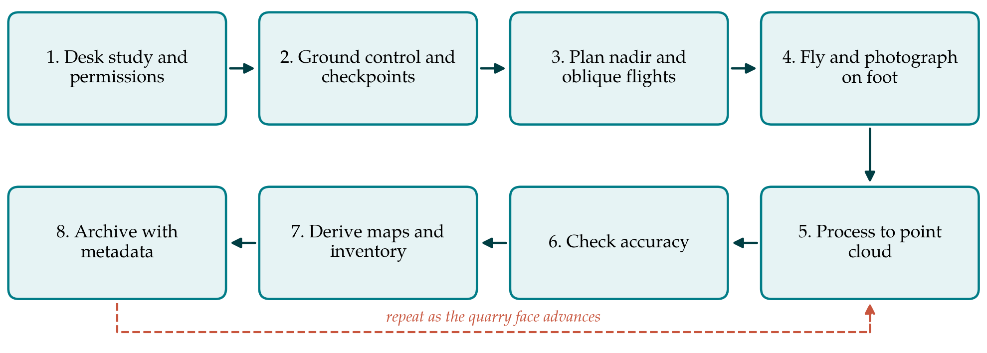
The procedure has eight steps, shown in sequence in Figure 1. The first three are preparation, the fourth is the field capture, and the last four turn photographs into a record that others can use. A return loop marks the repeat surveys that document the advance of a quarry.
3.1. Step 1: Desk study and permissions
Work starts with what is already known: earlier survey reports, district gazetteers, topographic sheets and free satellite imagery, on which the larger circles and cairns can often be seen. The limits of quarry leases and the direction of working are established from the mining authority or by observation, since they decide which part of the landscape is surveyed first. Permission is needed from the landowner, the archaeological authority and the aviation regulator. Rules differ between countries and change often. In India, for example, operations are governed by the Drone Rules (Ministry of Civil Aviation, 2021), which classify aircraft by weight and restrict flight in designated zones. An active quarry adds its own hazards, and blasting times must be known.
3.2. Step 2: Ground control and checkpoints
Targets that will be visible from the air, such as painted crosses on bedrock or printed boards pinned to the ground, are set out before flying and their positions measured. Their number and distribution matter more than any other single factor for the accuracy of the result (Sanz-Ablanedo et al., 2018). They should surround the survey area, include points in the interior and span its range of heights. A further set, the checkpoints, is measured in the same way but kept out of the processing so that it can test the result.
Survey-grade satellite positioning receivers are the ideal instrument and can often be borrowed from an engineering or geography department. Where none is available, a local grid can be established with a total station, or with careful taped distances between targets, which gives a model that is correct in scale and internally consistent though only approximately placed on the map. That is an acceptable compromise for a rescue record, provided it is stated.
3.3. Step 3: Flight planning
Flying height sets the ground sampling distance, the size of one pixel on the ground. For megaliths the aim is that a slab edge or a kerb stone is several pixels wide, which with a typical consumer camera means flying low. Flight lines are planned with high forward and side overlap, so that every point on the ground appears in many photographs. A second set of lines flown at right angles, with the camera tilted away from vertical, is planned as well. The oblique images strengthen the geometry of the block, counter the doming to which self-calibrated vertical blocks are prone (James and Robson, 2014), and show the sides of upright stones.
3.4. Step 4: Image capture from the air and on foot
Flights are made in even light, under thin cloud or within a short interval around midday, so that shadows do not move between flight lines. Exposure and focus are fixed, the shutter speed is kept fast and the aircraft slow. Images are saved at full resolution. Each battery covers a limited area, and the block is divided into overlapping sections accordingly.
The aircraft cannot see inside a chamber or under a capstone. Selected monuments, including every type present and any with port-holes, passages or carvings, are therefore photographed on foot with the same or a better camera, circling each at two or three heights with a scale bar in view. If these pictures overlap with the low oblique aerial images, the software can join the two sets in one model.
3.5. Step 5: Processing
Photographs are first sorted and blurred frames removed. Alignment produces camera positions and a sparse cloud. The control targets are marked in the images, and the bundle adjustment is run again with them as constraints. Dense matching then produces the point cloud from which a surface model and orthomosaic are generated. Whatever software is used, the settings, the version and the number of images are noted. General accounts of the workflow and its pitfalls are given by Smith et al. (2016).
3.6. Step 6: Accuracy checking
The coordinates of the checkpoints are read from the finished model and compared with their surveyed values. The differences are summarised as root mean square error in plan and in height and reported with the product. A check on the residuals at control points alone is not enough, because the adjustment has been fitted to them. If the checkpoint errors show a pattern, such as height error growing towards the edges, the block is reprocessed with different calibration settings or more images before any map is drawn.
3.7. Step 7: Maps, visualisation and inventory
The orthomosaic and elevation model are loaded into a geographic information system. Low cairns and robbed circles that are nearly invisible in a photograph often show clearly in the elevation model once it is displayed with a relief visualisation such as hillshading from several directions or the sky-view factor (Kokalj et al., 2011). Each candidate monument is digitised, given an identifier and described by type, dimensions and condition. Because natural boulder clusters mimic cairns, the inventory is verified on the ground with the map in hand before it is treated as final.
3.8. Step 8: Archiving and repeat survey
The record consists of the original photographs, the control and checkpoint coordinates, the processing report, the derived products and the inventory, together with a plain statement of how each was made. Professional guidance on photogrammetry for heritage stresses that the raw images are the primary archive, since they can be reprocessed as software improves (Historic England, 2017). Copies are lodged with the responsible archaeological authority and at least one other repository.
Where quarrying continues, the survey is repeated at intervals using the same control. Comparing successive elevation models shows where rock and monuments have been removed, and the dated sequence of orthophotographs provides evidence that can be put before a planning authority or a court.
4. Fitting the Procedure to Limited Means
The procedure assumes three or four people, one aircraft with spare batteries, borrowed survey equipment and a reasonably capable laptop. Training is the larger investment. Local volunteers and students can lay targets, clear loose vegetation and carry out ground photography after a day's instruction, and their knowledge of where monuments lie is often better than any map. Residents should be told what the aircraft is doing, and images that show people or private compounds should be handled with care.
5. Limitations and What Remains to Be Shown
No field test is reported here. The accuracy that the procedure delivers with a given aircraft on granite terrain, the smallest monument that can be recognised reliably in the elevation model, and the rate at which natural features are mistaken for cairns are all empirical questions. They could be answered by surveying a cemetery that has already been mapped by conventional means and comparing the two records monument by monument.
Some limits are inherent. Photogrammetry records surfaces. It says nothing of what lies in a chamber or beneath a cairn, and it cannot see through scrub. A digital record does not replace the monument, and its existence should never be offered as a reason to permit destruction. The procedure is intended to make sure that when protection fails, knowledge of the landscape does not disappear with the stone.
6. Conclusion
Megalithic landscapes on quarry land are being lost within the working lives of the people able to record them. Consumer drones and structure-from-motion software allow a small team to produce a measured, checkable record in days. The eight steps proposed here concentrate effort where inexpensive equipment is weakest: control, image geometry, independent accuracy checks and ground verification of the inventory. Field trials against conventional survey are the necessary next stage.
Conflict of interest
To be declared by the author(s) before publication.
Funding
To be declared by the author(s) before publication.