1. Introduction
In injection moulding the polymer melt must give up its heat to the mould before the part can be ejected. The time this takes rises with the square of the wall thickness of the part and depends on the thermal diffusivity of the polymer, and in most cycles it is longer than filling and packing together (Menges et al., 2001; Kazmer, 2016). Uniformity matters as much as speed. Where one region of the cavity runs hotter than another, the part shrinks unevenly, and the result is warpage, sink marks or residual stress. The cooling layout therefore decides both the productivity of the tool and the quality of what comes out of it.
Conventional moulds are cooled through gun-drilled holes, joined by plugs and supplemented by baffles and bubblers where a core is too slender for a through hole. Straight holes cannot follow a curved cavity. Some regions lie close to a channel and others far from one, and hot spots in deep cores, at corners and around inserts are a familiar result. The idea of channels that conform to the cavity is old, but it became practical only when tooling could be built additively. Sachs et al. (2000) produced inserts with conformal channels by three-dimensional printing of metal powder and showed more uniform mould temperatures than a drilled equivalent gave, and the subject has grown steadily since.
This review considers conformal cooling in inserts made by metal additive manufacturing. It is organised around the sequence a toolmaker follows: why conformal channels help, how they are designed, how the insert is built and finished, and how it behaves in service.
2. Approach of the Review
The article is a narrative review of the published literature and reports no new experiments. It relies on the early papers that established the concept, on later journal articles describing design methods and built inserts, on studies of the tool steels processed by laser powder bed fusion, and on earlier reviews of the field (Shayfull et al., 2014; Kanbur et al., 2020; Feng et al., 2021). Terminology for the processes follows the international vocabulary standard (ISO/ASTM, 2021). Coverage is selective and intended to represent the main lines of work, not to enumerate every study.
3. Why Conformal Channels Help
Heat leaves the cavity by conduction through the steel and by forced convection into the coolant. The conduction path is governed by the distance from cavity surface to channel wall and by the conductivity of the mould material. The convective side depends on the flow: turbulent flow gives a far higher heat transfer coefficient than laminar flow, and the standard correlations relate that coefficient to the Reynolds and Prandtl numbers (Bergman et al., 2011). A drilled layout fixes neither path well. A conformal layout holds the conduction distance nearly constant over the cavity and lets the designer place more channel length where the heat load is greatest.
Xu et al. (2001) gave the first systematic design treatment. They divided the tool into cooling zones, each served by its own channel, and set out the conditions a zone must satisfy: a transient condition, so that the mould surface reaches a steady cyclic temperature within a few shots; limits on coolant temperature rise and pressure drop along the channel; and a check that the steel between channel and cavity can carry the injection pressure. Their analysis also explained an effect that was at first surprising, namely that a conformally cooled tool with low thermal mass near the cavity settles to its operating temperature much faster than a conventional one. Later studies comparing drilled and conformal layouts by simulation and by trial, such as that of Dimla et al. (2005), generally report shorter cooling times and smaller temperature differences across the cavity, although the size of the benefit depends strongly on part geometry.
4. Design Methods
Design methods have moved from rules of thumb toward automation. The simplest guidance is dimensional: channel diameter, the pitch between channels and the depth below the cavity surface are chosen in proportion to the wall thickness of the moulded part, in tables that carry over from drilled tooling (Kazmer, 2016). Such rules give a starting layout but say nothing about how to route a channel over a free-form surface.
Several geometric algorithms address routing. Au et al. (2011) generated channels from a visibility analysis of the cavity surface, treating each stretch of channel as a source that must be able to "see" the region it cools. Wang et al. (2011) offset the cavity surface, partitioned the offset with a centroidal Voronoi diagram and took the cell boundaries as a channel network, which yields a circuit automatically for complex shapes. The same group later proposed spiral channels wound along the offset surface, arguing that a single spiral avoids the uneven flow division of a branched network (Wang et al., 2015). Park and Dang (2010) combined conformal channels with arrays of baffles and optimised their dimensions, a hybrid that can be made partly by conventional means.
A different line abandons discrete channels. Au and Yu (2007) proposed a porous scaffold beneath the cavity surface through which coolant floods, so that nearly the whole surface is cooled from behind, and Brooks and Brigden (2016) designed conformal cooling layers filled with self-supporting lattices that carry the injection pressure while leaving a large wetted area. Optimisation frameworks have followed. Wu et al. (2015) set out a procedure that couples thermal and mechanical analysis with topology optimisation of the insert, and parametric studies of channel size, pitch and depth are now a routine part of such work. The main design families are compared in Table 1.
| Approach | How the layout is obtained | Strength | Limitation |
|---|---|---|---|
| Spacing rules | Diameter, pitch and depth scaled to part wall thickness Kazmer, 2016 | Quick; familiar to toolmakers | No routing on free-form surfaces |
| Cooling zones | Tool divided into zones meeting thermal and pressure conditions Xu et al., 2001 | Physically reasoned design windows | Zone layout still chosen by hand |
| Geometric routing | Visibility or Voronoi partition of an offset surface Wang et al., 2011 | Automatic circuits on complex shapes | Flow balance in branched networks |
| Spiral channels | Single channel wound along the offset surface Wang et al., 2015 | One flow path, even coolant velocity | Long path, higher pressure drop |
| Scaffold or lattice layers | Porous region floods behind the cavity Brooks and Brigden, 2016 | Large wetted area, uniform cooling | Powder removal and cleaning |
| Simulation-led optimisation | Coupled thermal and structural analysis with optimisation Wu et al., 2015 | Balances cooling against strength | Computing effort; model assumptions |
All of these methods rest on simulation for verification. Commercial moulding software solves the transient heat conduction in mould and part together with the coolant flow, and the predicted mould surface temperature field and part warpage are the usual measures of merit. The reviews agree that simulation predicts the relative ranking of layouts reliably, while absolute cycle times depend on boundary conditions, such as contact resistance at the polymer and mould interface, that are hard to know in advance (Kanbur et al., 2020; Feng et al., 2021).
5. Building the Insert
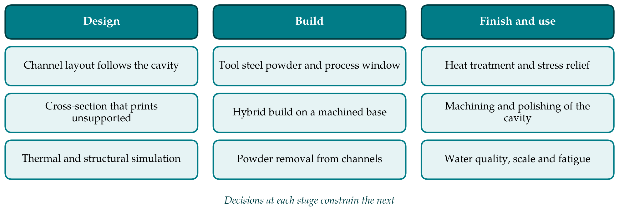
An insert with internal channels has to be designed for the process that builds it, and the choices made at one stage restrict those available at the next. Figure 1 groups the main decisions into design, build and finishing, and the following subsections take the build and finishing stages in turn.
5.1. Processes and materials
Early conformal tooling used binder-based printing followed by sintering and infiltration (Sachs et al., 2000), and inserts have also been made by electron beam melting (Rannar et al., 2007) and by laser deposition processes. Laser powder bed fusion now dominates, because it gives the finest features and nearly full density in tool steels (Gibson et al., 2015). The development of the process for iron-based powders is described by Kruth et al. (2004).
Two steel families are used most. Maraging steel of the 18Ni-300 type is the easier to process: it contains almost no carbon, forms a soft martensite on cooling and is hardened afterwards by an ageing treatment, so it builds with little cracking. Kempen et al. (2011) characterised its microstructure and mechanical properties after laser melting and after ageing. The hot-work steel H13, the standard material for conventional mould inserts, is harder to build because its carbon martensite is brittle and the residual stresses of the process are high; Mertens et al. (2016) showed that preheating the powder bed changes the microstructure and reduces the tendency to crack. Mazur et al. (2016) built H13 specimens with conformal channels and lattice structures and documented the achievable geometry. The thermal conductivity of both steels is modest, which strengthens the argument for placing channels close to the cavity.
5.2. Geometric limits and hybrid builds
The powder bed supports a downward-facing surface only weakly. Overhangs shallower than roughly 45 degrees to the build plate need support structures, and supports inside a closed channel cannot be removed. Design rules derived for the process therefore limit the diameter of a horizontal circular channel that will build without sagging, and recommend teardrop, elliptical or diamond sections for larger channels (Thomas, 2009). The as-built channel wall is rough, with partly fused powder adhering to the roof. Roughness raises pressure drop and, in turbulent flow, also raises heat transfer, so its net effect is not simply harmful, but it is a likely site for fatigue cracks to start.
Building a whole insert additively is slow and costly, and most of its volume needs no internal features. A common practice is the hybrid build: the lower part of the insert is machined from wrought tool steel, and only the region near the cavity, containing the conformal channels, is built on top of it by powder bed fusion. The joint must be sound, the drilled supply holes in the base must register with the printed channels, and the two materials must respond acceptably to one heat treatment. Trapped powder has to be cleared before any stress relief, since heating sinters loose powder in place.
5.3. Finishing
An insert leaves the machine near net shape but not finished. The cavity surface is machined and polished or textured to the specification of the moulded part, which requires stock allowance and, for optical finishes, a material free of porosity at the surface. Heat treatment follows the steel: ageing for maraging grades, tempering or a full quench and temper for H13. Mazur et al. (2017) carried a conformally cooled H13 mould through this whole sequence and compared its measured thermal behaviour with simulation, one of the fuller accounts in the literature of design, manufacture and test together.
6. Behaviour in Service
A mould insert is loaded cyclically by injection pressure and clamp force and thermally by the alternation of melt and coolant. A channel close to the cavity leaves a thin ligament of steel that sees both. The cooling-zone analysis of Xu et al. (2001) included a strength check for this reason, and later optimisation frameworks treat stress as a constraint alongside temperature (Wu et al., 2015). Published fatigue data for additively built tool steels with as-built channel surfaces are still limited, and the reviews note that few studies follow inserts through long production runs (Feng et al., 2021).
Water-side degradation is the other concern. Maraging steel is not stainless, and narrow channels with rough walls are prone to corrosion and to deposits of scale, both of which reduce heat transfer and can eventually block the flow. Conformal channels cannot be re-drilled or easily inspected. Treated or closed-loop water, filtration, corrosion inhibitors and periodic flow checks are the usual precautions, and some toolmakers apply internal coatings. The literature on these measures is largely practical and sparse, which is a weakness given that the economic case for a conformal insert assumes that it lasts as long as a drilled one.
7. Gaps and Future Work
Three gaps stand out. The first is service evidence. Laboratory comparisons of cooling time and temperature uniformity are plentiful, while reports of fatigue life, corrosion and maintenance over production volumes are rare. The second is the economics. Shorter cycles and less scrap have to be set against the cost of the build, the powder, the finishing and the risk of an insert that cannot be repaired, and the balance differs between a thin-walled packaging part and a thick technical moulding. Few studies present the calculation in a form that can be transferred to other parts.
The third gap is in design automation. Geometric routing methods, lattice concepts and topology optimisation each solve part of the problem, but none yet delivers a layout that is thermally balanced, structurally safe, printable without internal supports and free of trapped powder, without substantial manual intervention. Bringing the manufacturing rules of powder bed fusion into the optimisation as constraints, and validating the results on inserts taken through to production, would close much of the distance between research and toolroom practice. Tool steels with higher thermal conductivity developed for additive processing also deserve systematic evaluation.
8. Conclusion
Additive manufacturing has turned conformal cooling from an attractive idea into a routine option for mould inserts. The thermal case is well founded: holding channels at a constant distance from the cavity shortens cooling and evens out mould temperature, and design methods now exist that generate such layouts for complex shapes. The remaining uncertainties are those of manufacture and service, including channel surface condition, the joint in hybrid builds, fatigue of thin ligaments and the slow effects of corrosion and scale. Progress on those questions, more than further refinement of thermal design, will decide how widely conformal inserts are adopted.
Conflict of interest
To be declared by the author(s) before publication.
Funding
To be declared by the author(s) before publication.