1. Introduction
Aerospace ribs, turbine casings, impeller blades and many electronic housings are machined from solid stock down to walls a millimetre or two thick. The economic case for doing so is strong, since a monolithic part replaces an assembly, but the machining is slow. As the wall thins, its stiffness falls with the cube of the thickness, and the wall becomes the weakest spring in the loop that joins tool and workpiece. Two problems follow. The wall deflects statically under the cutting force and is left oversize, a matter analysed in detail by Budak and Altintas (1995). It also vibrates, and under the wrong conditions the vibration sustains itself and grows into chatter.
Chatter leaves a marked surface, shortens tool life and can scrap a part into which many hours of roughing have already gone. The standard reviews of the subject list the available countermeasures: choose spindle speeds in the stable pockets between lobes, disturb the regeneration with variable pitch or variable speed, or change the structure by adding stiffness or damping (Quintana and Ciurana, 2011; Munoa et al., 2016). For thin walls the last group is especially attractive, because the troublesome mode belongs to the part and is very lightly damped, so that a modest amount of added damping buys a large increase in the stable depth of cut.
A tuned mass damper is a small mass on a spring and a dashpot, attached to the vibrating structure and tuned close to the frequency of the offending mode. It needs no power and no controller. Placing it in the fixture, pressed against the back of the wall or built into a support, keeps it out of the way of the cutter and lets it be reused from part to part. This review examines what the literature says about that arrangement: the theory behind it, the devices that have been described, and the points on which designers still lack guidance.
2. Scope and Approach
This is a narrative review of the published literature. It draws on the foundational papers on regenerative chatter and on vibration absorbers, on the review articles of the International Academy for Production Engineering, and on journal papers that describe absorbers or related damping devices applied to flexible workpieces and their fixtures. No claim of exhaustive coverage is made, and no new experiments or simulations are reported. Work on absorbers fitted to boring bars, spindles and machine structures is mentioned where the tuning theory was first developed there, but the emphasis is on the workpiece side.
3. Regenerative Chatter and the Flexible Workpiece
The explanation of chatter that is used today dates from the 1950s and 1960s. Tobias and Fishwick (1958) and Tlusty and Polacek (1963) showed independently that the vibration regenerates: a tooth cuts a surface left wavy by the previous tooth, so the chip thickness, and with it the force, depends on the present vibration and on the vibration one tooth period earlier. Merritt (1965) recast the argument as a feedback loop, which made the stability limit a matter of ordinary control theory. The well known result for a single mode is that the limiting depth of cut is inversely proportional to the most negative value of the real part of the frequency response function at the cutting point.
Milling complicates the picture because the force direction rotates and the cut is interrupted. Altintas and Budak (1995) gave an analytical solution based on the average term of the Fourier expansion of the directional coefficients, which remains the usual way to draw stability lobes. For the low radial immersions typical of wall finishing, where the tooth is in the cut for a short part of each revolution, time-domain or semi-discretisation methods are more accurate (Insperger and Stepan, 2004). Textbook treatments are given by Altintas (2012) and Schmitz and Smith (2009), and the state of knowledge up to the early 2000s was summarised by Altintas and Weck (2004).
With a thin wall the dominant flexibility moves from the tool to the part. Bravo et al. (2005) treated the case where machine and workpiece are both compliant and proposed stability diagrams with a third axis for the stage of machining, because the wall's modal parameters change as it is cut. Thevenot et al. (2006) made the same point for peripheral milling of plates, showing how material removal shifts the natural frequencies and with them the lobes. The response also varies along the wall: near a free edge or at an antinode the part is compliant, near a node it is stiff, and Seguy et al. (2008) related the resulting bands of good and bad surface to the interaction of several plate modes. Any damping device for a thin wall therefore faces a structure whose frequency, mode shape and effective mass all vary during the operation.
4. Tuned Mass Dampers: Classical Theory and Its Adaptation to Chatter
The dynamic vibration absorber began as an undamped device, effective at a single frequency, and Ormondroyd and Den Hartog (1928) showed that adding damping to it widens the band over which it works. The tuning rule found in every vibration textbook comes from this line of work: for an undamped primary system, the amplitude of the response is minimised when the two peaks of the modified response are made equal in height, which fixes the frequency ratio and the damping ratio of the absorber as functions of the mass ratio alone (Den Hartog, 1956). The rule assumes a steady harmonic force and a primary structure whose properties do not change, two assumptions that the milling of a thin wall does not satisfy.
Equal-peak tuning minimises the magnitude of the response, which is the right target under forced vibration. Chatter depends on the real part. Sims (2007) set out this distinction clearly and derived an analytical tuning that flattens the negative real part of the response instead of its magnitude; the absorber is tuned somewhat higher in frequency than the classical rule suggests, and the predicted gain in limiting depth of cut is considerably larger for the same added mass. The idea was extended numerically to several absorbers by Yang et al. (2010), who optimised a set of small dampers with staggered frequencies so as to minimise the largest negative real part. Spreading the mass over several units costs little in peak performance and makes the result less sensitive to errors in tuning, a property of obvious value when the target frequency is uncertain.
Two other strands of absorber research are relevant. One is the absorber with more than one degree of freedom: Zuo and Nayfeh (2006) showed that a single body allowed to translate and rotate can outperform a conventional absorber of the same mass on a single mode, which matters where space is tight. The other is the long experience with absorbers in cutting tools. Tarng et al. (2000) mounted a tuned absorber on a turning tool and reported a clear rise in the stable limit, and damped boring bars built on the same principle have been commercial products for decades (Munoa et al., 2016). The theory, then, is mature. What is particular to thin walls is the behaviour of the structure to which the absorber is attached.
5. Devices Applied to Thin-Walled Parts and Their Fixtures
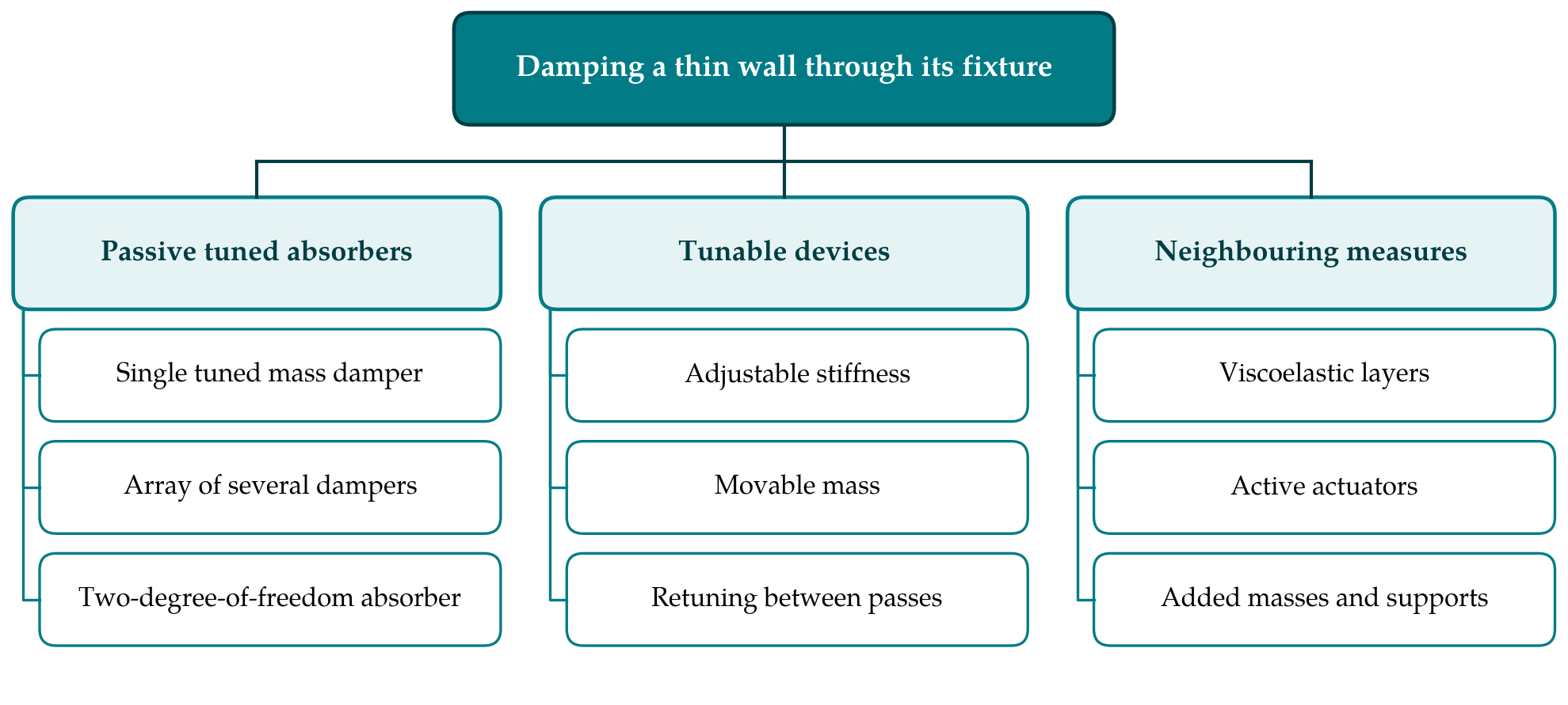
Published devices fall into three groups, set out in Figure 1: passive absorbers of fixed tuning, devices whose tuning can be adjusted, and neighbouring measures that share the aim of adding damping or shifting the mode through the fixture. Table 1 compares the main options against the demands of a thin wall.
| Measure | Principle | Main strength | Main limitation |
|---|---|---|---|
| Single tuned mass damper | Auxiliary mass tuned near the wall mode | Simple, unpowered, large gain when tuned | Loses effect as the wall frequency drifts |
| Multiple tuned dampers | Several small masses with staggered tuning Yang et al., 2010 | Broader band, tolerant of tuning error | More parts to place behind the wall |
| Tunable passive damper | Stiffness or mass position reset between passes | Follows the changing mode | Needs a schedule of settings per part |
| Viscoelastic treatment | Constrained polymer layer or damped masses Kolluru et al., 2013 | Acts on many modes at once | Properties vary with temperature and frequency |
| Active damping | Sensor, controller and actuator on the part Zhang and Sims, 2005 | Adapts automatically | Cost, wiring, actuator force and stroke |
| Added mass or support | Shifts or stiffens the mode Wan et al., 2018 | No tuning required | Adds little damping; access may be blocked |
5.1. Passive absorbers of fixed tuning
Rashid and Nicolescu (2008) designed tuned viscoelastic dampers, in which a polymer element supplies both the spring and the loss, and applied them to a workpiece held in a milling fixture. They reported a marked reduction in vibration amplitude and discussed how the frequency-dependent properties of the polymer enter the tuning. Kolluru et al. (2013) dealt with thin-walled casings of the kind used in aero engines and attached discrete masses through a viscoelastic layer to the surface of the casing, with the aim of treating several closely spaced modes at once. Bolsunovsky et al. (2013) described a dynamic support, a fixture element pressed against a flexible workpiece and designed to behave as a tuned mass damper, which is the arrangement closest to the subject of this review.
5.2. Tunable devices
A fixed absorber is correct at one stage of the cut. Because the wall loses mass and stiffness as it is machined, its frequencies move, and an absorber tuned for the blank is mistuned for the finished part. The response in the literature has been to make the absorber adjustable, for example by changing the free length of a cantilever spring or the position of the mass, and to reset it between passes according to a schedule derived from a finite element model of the part at each stage. The approach keeps the device passive during cutting, which preserves its simplicity, but it shifts effort into process planning: the modal properties of the part have to be predicted or measured at every step for which a setting is required.
5.3. Neighbouring fixture measures
Absorbers compete with other ways of using the fixture. Supporting a thin, compliant workpiece at many points raises its stiffness directly and is the oldest remedy of all. Wan et al. (2018) attached additional masses to a thin-walled workpiece and optimised their positions so as to move the stability lobes and enlarge the stable region, a method that alters frequency and modal mass without relying on damping. Zhang and Sims (2005) examined the feasibility of active damping of a workpiece with piezoelectric elements and showed that useful increases in the stability limit are possible, at the price of sensors, amplifiers and a controller.
6. Design Questions That Recur
Four questions come up in almost every paper. The first is mass ratio. Classical theory says that performance improves with the ratio of absorber mass to modal mass, with diminishing returns, and that a larger ratio also widens the tolerance on tuning. On a thin wall a small auxiliary mass is enough to reach ratios that would be impractical on a machine column. The limit is set by space behind the wall and by the static load the absorber and its contact place on the part.
The second is placement. An absorber works on a mode in proportion to the square of the mode shape at its attachment point, so it belongs at an antinode, and an absorber at a node does nothing. Thin walls have several modes within the range excited by the tooth passing frequency and its harmonics, with antinodes in different places, which is one argument for several small absorbers over a single large one.
The third is the contact between a fixture-mounted absorber and the part. A device that is bolted or bonded to the wall is modelled easily, but a device that is merely pressed against it relies on preload and friction, and the joint has stiffness and damping of its own. Few papers characterise this interface, although it decides whether the absorber sees the motion of the wall at all. The fourth is robustness. Tuning for the real part gives more stability at the design point than equal-peak tuning does, but the optimum is narrow, and the comparisons made by Sims (2007) and Yang et al. (2010) indicate that sensitivity to detuning should be treated as a design criterion alongside peak performance.
7. Gaps and Directions for Further Work
The literature shows convincingly that absorbers raise the chatter limit of thin walls. It is less helpful to a fixture designer who must decide what to build for a new part. Reported devices are mostly demonstrated on plates or simple casings, each with its own geometry, cutter and material, and the gains are expressed in different terms, so results cannot be compared directly. A shared set of benchmark workpieces and a common way of reporting improvement, for instance the ratio of limiting depths of cut at stated speeds, would make the body of evidence far more useful.
Time variation is the second gap. Tuning theory assumes a fixed primary system. For a wall whose frequency falls or rises during the cut, the designer needs either a rule for choosing a compromise tuning or a method for scheduling adjustments, and neither has been stated in a general form. Linking the absorber design to models that predict the part dynamics throughout material removal, of the kind proposed by Thevenot et al. (2006), is an evident next step.
8. Conclusion
Tuned mass dampers suit thin-wall milling for a simple reason: the troublesome modes are light and lightly damped, so a small auxiliary mass has a large effect. The theory needed to tune such devices for chatter, as distinct from forced vibration, has been available since the work on real-part tuning, and several fixture-mounted and part-mounted devices have been shown to work. What the literature does not yet provide is a general procedure for a structure that changes as it is cut, or a common basis for comparing devices. Until those are supplied, each application will continue to be engineered case by case, guided by the principles reviewed here.
Conflict of interest
To be declared by the author(s) before publication.
Funding
To be declared by the author(s) before publication.