1. Introduction
Green sand moulding is the oldest and still the cheapest way to make an iron or aluminium casting in quantity. Silica sand bonded with bentonite clay and water is compacted around a pattern, the pattern is withdrawn, cores are set and the mould is closed and poured. The sand is then shaken out, cooled, rebonded and used again (Beeley, 2001; Brown, 2000). The foundry clusters of South India, of which Coimbatore in Tamil Nadu and Belgaum in Karnataka are the best known, are largely built on this process and on the small and medium-sized firms that practise it.
The limitation of green sand lies in the pattern. Every new casting needs pattern equipment and core boxes, the shapes that can be drawn from the sand are restricted by draft and parting lines, and skilled patternmakers are becoming harder to find. Binder jetting removes the pattern. A printer spreads a thin layer of sand, a print head deposits binder where the mould is to be solid, and the cycle repeats until the mould or core is complete (Sachs et al., 1992). The process, classed as binder jetting in the additive manufacturing vocabulary (ISO/ASTM, 2021), has been used commercially for sand moulds for about two decades (Upadhyay et al., 2017).
For a small foundry the question is seldom whether printed moulds work. It is whether, for which jobs and in what form they make sense for a business with limited capital. This article proposes a procedure for reaching that decision. It is a methodological guide assembled from foundry practice and the literature. It does not report the experience of any actual foundry, and it has not been tested in use.
2. Background
The two processes differ in more than the absence of a pattern, and the differences drive every step of the procedure. Table 1 sets the main ones side by side.
| Aspect | Green sand mould | Binder jet mould | Consequence for planning |
|---|---|---|---|
| Tooling | Pattern and core boxes for each part | None; built from a CAD model | Fixed cost falls, cost per mould rises |
| Binder | Bentonite clay and water | Organic resin, commonly furan or phenolic | More gas on pouring; fume control needed |
| Geometry | Limited by draft, parting and core prints | Undercuts and integral cores possible | Rigging can be redesigned freely |
| Sand | Wide range tolerated; reclaimed in house | Narrow grain size; dry and free-flowing | Sand supply must be qualified |
| Accuracy and finish | Depends on pattern wear and ramming | Set by layer thickness and grain size | Trial castings needed to confirm |
| Used sand | Returned to the system sand | Chemically bonded; separate stream | Reclamation or disposal route required |
| Skills | Moulding and patternmaking | CAD, printer operation, depowdering | Training plan required |
The most common binder system for printed moulds is furan no-bake: the sand is pre-coated with an acid activator and the print head jets furfuryl alcohol resin, which cures at room temperature. Phenolic and inorganic systems are also offered (Sivarupan et al., 2021). Printed furan moulds are strong and dimensionally stable, but they contain more binder than a conventional no-bake mould would for the same strength, and that binder decomposes to gas when metal is poured. Permeability and venting therefore need attention, as reviews of the technology point out (Upadhyay et al., 2017; Kang and Ma, 2017).
The economics are those of any additive process set against a tooled one. A conventional mould is cheap once the pattern exists, so cost per casting falls steeply with quantity. A printed mould costs much the same whether one or one hundred are made, and its cost follows the volume of sand printed and the machine time. This pattern was described early for polymer parts (Hopkinson and Dickens, 2003; Ruffo et al., 2006) and for metal parts (Atzeni and Salmi, 2012). For sand moulds, Almaghariz et al. (2016) showed that the break-even point depends on part complexity: the more cores and loose pieces a casting needs, the larger the quantity up to which printing remains competitive.
3. The Proposed Procedure
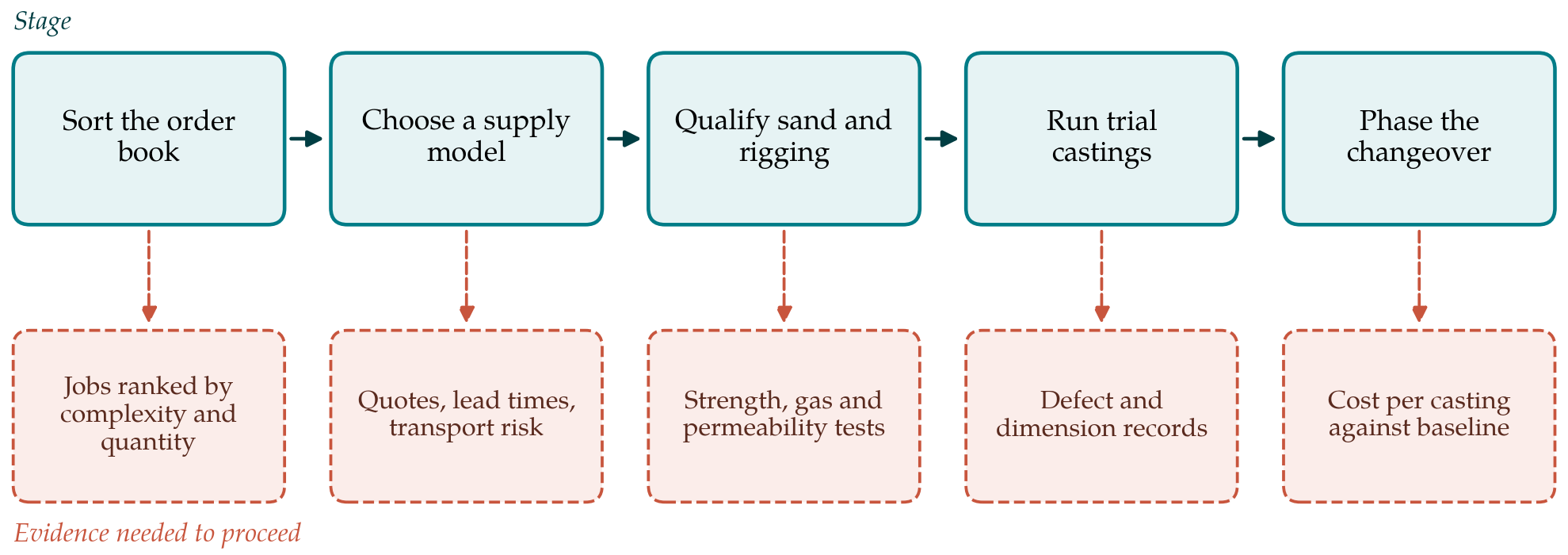
The procedure has eight steps grouped into five stages. Figure 1 shows the stages and the evidence that should be in hand before moving from one to the next. The intention is that a foundry can stop at any stage with a clear reason and without having committed capital prematurely.
3.1. Step 1: Sort the order book
The starting point is the foundry's own work. Every active casting is listed with its annual quantity, the number of cores, the state of its pattern equipment and its recent scrap history. Jobs then fall into three groups: repeat work in quantity on sound patterns, which should stay in green sand; prototypes, one-off spares and jobs whose patterns are worn out or lost, which are candidates for printing; and heavily cored castings such as pump volutes, impellers and manifolds, where printed cores might cut assembly labour and core-related scrap. A map of products by volume and complexity, of the kind proposed for additive manufacturing generally (Conner et al., 2014), is a convenient way to display the result.
3.2. Step 2: Choose a supply model
Three models are available. The foundry can buy printed moulds and cores from a service bureau, own a printer, or adopt a hybrid in which printed cores are set in conventional green sand moulds. The guide recommends that a small foundry begin with bought-in cores for a few jobs. This needs no capital, tests customer interest and exposes the practical problems. Printed sand parts are fragile and bulky, so transport distance, packaging and breakage in transit must be weighed, as must the lead time from order to delivery. Ownership becomes worth examining only when the volume of printed sand bought each month would keep a machine reasonably busy. Shared ownership through a cluster facility is a further option where an industry association exists to host it.
3.3. Step 3: Redesign the rigging
A printed mould should not be a copy of the green sand one. Freedom from draft and parting lines allows runners that fill from the bottom with less turbulence, feeders placed where solidification requires them, and cores consolidated into single pieces. The principles of quiescent filling and directional feeding set out by Campbell (2015) apply with fewer compromises, and published demonstrations show complex gating and cellular geometries made this way (Snelling et al., 2015). Two cautions follow from the binder content: vents must be generous, and the mould should be designed as a shell of modest wall thickness, supported by loose backing sand if necessary, to limit both gas and the volume of costly printed sand. Solidification simulation, described for foundry engineers by Ravi (2005), is well suited to checking the new layout before anything is printed.
3.4. Step 4: Qualify sand and binder
Printers need dry, rounded sand within a narrow size range, and the foundry must establish whether a regional silica sand meets the supplier's specification or whether sand must be bought through the machine vendor. Test pieces printed in the candidate sand are checked by the standard foundry tests for bending or tensile strength, permeability, loss on ignition and gas evolution (ASM International, 2008). Climate deserves a specific test. Organic binders are sensitive to humidity, and much of South India has a long monsoon season with humid air. Strength should therefore be measured after storage for periods and conditions that match the foundry's own stores, and packaging or a dry room specified if it falls.
3.5. Step 5: Run trial castings
Acceptance criteria are agreed before the first trial is poured: dimensional tolerance, surface roughness, soundness by the customer's inspection standard, and freedom from the defects to which resin bonded moulds are prone, namely gas porosity, veining and metal penetration. Each trial casting is made alongside a green sand casting of the same part in the same melt where this is possible, so that differences can be attributed to the mould. The records kept are the defect type and location, the dimensions and the fettling time. Published comparisons of printed and conventional moulds indicate what to look for (Hawaldar and Zhang, 2018; Chhabra and Singh, 2011), but they do not substitute for the foundry's own alloy and section sizes.
3.6. Step 6: Build the cost model
The model compares cost per good casting by each route. For green sand it includes the pattern and core boxes spread over the expected order quantity, moulding and core-making labour, sand preparation and scrap. For printing it includes the price of printed sand by volume, transport, any redesign time, and the same melting and finishing costs adjusted for the trial results. Plotting both against quantity gives a break-even point for each job. Where an owned printer is under study, depreciation, maintenance contracts, imported consumables priced in foreign currency and the cost of an uninterrupted power supply are added, and the machine utilisation assumed should be stated openly, since idle time dominates the cost of additive equipment (Ruffo et al., 2006).
3.7. Step 7: Deal with used sand and fume
Furan-bonded sand cannot simply be returned to the clay-bonded system in quantity, because binder residues and acid alter the properties of the green sand. A small proportion of core sand is diluted in any foundry's system, but a planned increase needs monitoring of the system sand and, beyond some point, a separate route: mechanical or thermal reclamation, or disposal through a channel acceptable to the state pollution control board. Pouring and shake-out of resin-bonded moulds release decomposition products, so local extraction at those stations should be reviewed, and the handling and storage rules for the resin and activator obtained from the supplier's safety data sheets.
3.8. Step 8: Phase the changeover
The final step is a timetable. A first phase limited to bought-in cores for selected jobs is followed by a review against the cost model and the scrap record. Only if the review is favourable does the foundry move to complete printed moulds for prototypes, and only after that to any discussion of ownership. Training runs in parallel. At least one person needs to be competent in three-dimensional modelling and mould design, and moulders need to learn the handling, cleaning and assembly of printed parts. Green sand moulding continues throughout for the work it suits.
4. Fitting the Procedure to Practice
The title of this article speaks of a switch, and the procedure deliberately turns that into a partial and reversible change. For most small foundries the realistic outcome is a mixed shop: green sand for volume, printed cores for difficult castings and printed moulds for urgent one-offs. A foundry serving the replacement market for pumps and textile machinery, where patterns for old designs no longer exist, will weight Step 1 differently from one that supplies automotive components on long contracts. The order of the steps matters more than the detail of each.
5. Limitations and What Remains to Be Shown
This guide is a proposal. It has not been followed by a foundry and reported, and it contains no cost figures, because prices of printed sand, machines and labour vary by supplier and year and any number given here would soon mislead. Its recommendations rest on general foundry principles and on studies conducted mostly in other countries. Whether the hybrid route reduces scrap for cored castings under South Indian shop conditions, how printed moulds stored through a monsoon behave, and at what throughput a shared printer becomes viable for a cluster are empirical matters. Documented applications of the procedure, with before-and-after records, would be the appropriate test.
6. Conclusion
Binder jet moulds offer a small green sand foundry freedom from patterns at the price of a costlier mould and a different chemistry. The eight-step procedure proposed here begins with the order book, favours bought-in printed cores as a first move, and makes each later commitment depend on evidence from sand tests, trial castings and a cost model. It treats used sand, fume and training as part of the decision and leaves green sand in place where it remains the better process. The procedure is offered for trial and correction by those who run foundries.
Conflict of interest
To be declared by the author(s) before publication.
Funding
To be declared by the author(s) before publication.