1. Introduction
Since methylammonium lead halide perovskites were first used as light absorbers in solar cells (Kojima et al., 2009), the same materials have been turned to light detection. Their absorption is strong across the visible range, carriers travel far even in solution processed films, and photodiodes with high detectivity were reported within a few years (Dou et al., 2014). Reviews of the field describe photoconductors, photodiodes and phototransistors on rigid and flexible supports (Ahmadi et al., 2017), and a flexible broadband photoconductor on a polymer film was shown early (Hu et al., 2014).
Paper extends this line. Its appeal as an electronic substrate, set out by Tobjörk and Österbacka (2011), lies in cost, recyclability and compatibility with roll fed printing. A photodetector made by printing two electrodes on paper and coating a perovskite film between them needs no vacuum step and no lithography. The simplicity invites quick first measurements, and those are the measurements most at risk of error. This note describes how such a campaign might be planned. It presents no experimental results.
2. What Paper and Printed Electrodes Change
Three properties of paper bear on the measurement. Its surface is rough on the scale of the cellulose fibres, many times the thickness of a perovskite film, so the film is discontinuous unless the paper is coated or calendered. It is porous, so inks and precursor solutions wick into the bulk and the active layer may lie partly inside the sheet. And it takes up water from the air, which raises its own conductivity and brings moisture into contact with a material that degrades in humid conditions (Leijtens et al., 2015).
Printed electrodes add their own features. Silver flake inks and carbon pastes have sheet resistances well above those of evaporated metal, and their edges are ragged, so the channel length of a planar device varies along its width. Carbon is chemically compatible with halide perovskites and has been used as a printed back contact in solar cells (Mei et al., 2014), whereas silver can react with halide species over time. With such contacts the device is in most cases a planar photoconductor, a geometry that readily shows gain and, with it, slow response and large dark current (García de Arquer et al., 2017).
3. A Proposed Measurement Sequence
Figure 1 pairs each measurement in the proposed sequence with the hazard that the paper substrate or the printed contacts introduce. The sequence runs from the least to the most disturbing measurement, so that the device is characterised in the dark before it is stressed by light and bias.
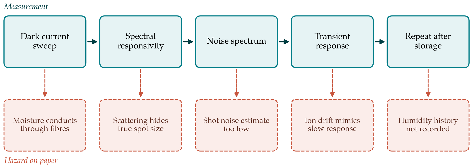
The dark current comes first. A control sample, the same printed electrodes on the same paper without perovskite, should be measured beside the device at a recorded relative humidity, since conduction through damp paper can rival the current through the film. Voltage sweeps should be made in both directions and at more than one sweep rate. Hysteresis between the forward and reverse sweeps is the signature of ion migration familiar from perovskite solar cells (Snaith et al., 2014), and where it is present a single quoted dark current has little meaning without the sweep conditions.
Responsivity, the photocurrent per unit of incident optical power, requires the power falling on the active area to be known. On paper two difficulties arise. The active area of a device with ragged electrodes has to be measured under a microscope and not taken from the print design, and light scattered within the sheet can generate carriers outside the nominal channel. The irradiance should be set with a calibrated reference photodiode at the sample position, and responsivity should be reported across several decades of irradiance, because photoconductive gain falls as intensity rises and a single low intensity value overstates performance under working conditions.
Specific detectivity is the figure most often misreported. It combines responsivity with the noise current, normalised to area and bandwidth. A common shortcut assumes that the noise is the shot noise of the dark current, which ignores flicker and thermal noise and can overstate detectivity by orders of magnitude. Fang et al. (2019) recommend measuring the noise spectrum directly, with a low noise amplifier and a spectrum analyser in a shielded enclosure, and quoting detectivity at a stated frequency. A resistive printed contact and a fibrous substrate both favour flicker noise, so the advice applies with particular force. Table 1 lists the quantities to be reported with the conditions that must accompany each.
| Quantity | How it is obtained | Conditions to state |
|---|---|---|
| Dark current | Voltage sweeps in both directions, with a bare paper control | Sweep rate, humidity, temperature |
| Responsivity | Photocurrent divided by optical power on the measured active area | Wavelength, irradiance, bias, area method |
| Noise current | Measured noise spectral density in a shielded enclosure | Frequency, bias, amplifier noise floor |
| Specific detectivity | From responsivity and measured noise, not shot noise alone | Frequency and bandwidth used |
| Response time | Rise and fall under modulated light; frequency response | Load resistance, light level, definition used |
| Linear dynamic range | Photocurrent against irradiance over several decades | Limits set by noise and by saturation |
| Stability | Repeat of all quantities after storage and after bending | Atmosphere, duration, bend radius |
Response time is measured with a modulated source, and the rise and fall times are read between stated fractions of the step. Perovskite photoconductors often show a fast electronic component followed by a slow tail from trap filling and ion drift, and quoting only the fast part flatters the device. The frequency at which the response falls by 3 dB gives an independent check. Finally the whole set is repeated after storage in a recorded atmosphere and after a stated number of bending cycles, since foldability is the reason for choosing paper.
4. Reporting and Safety
A first report is most useful to others when it allows the device to be compared with those on glass or plastic. That requires the control measurement on bare paper, the number of devices made and the number that worked, and the spread between them as well as the best case. Textbook definitions of the figures of merit should be followed (Sze and Ng, 2007), and any departure from them stated.
Lead content deserves a remark of its own. Paper devices are often described as disposable, but a lead halide perovskite on a porous, combustible, water absorbing sheet is a poor candidate for casual disposal, and the hazards of lead release from perovskite devices have been set out clearly (Babayigit et al., 2016). Encapsulation and an end of life route belong in the design from the first prototype.
5. Conclusion
A perovskite photodetector with printed electrodes on paper can be made with very simple means, and its first measurements need more care than its fabrication. A bare paper control, bidirectional sweeps, a measured active area, a directly measured noise spectrum and a record of humidity separate a result that others can build on from one that cannot be interpreted. The sequence proposed here is a checklist drawn from the literature and remains to be tried in practice.
Conflict of interest
To be declared by the author(s) before publication.
Funding
To be declared by the author(s) before publication.