1. Introduction
An airliner structure is certified on the principle of damage tolerance: cracks and corrosion are assumed to occur, and inspections are scheduled so that damage is found before it reduces strength below the required level (Swift, 1994; FAA, 2011). As an aircraft ages, the inspection programme expands. Supplemental structural inspections, corrosion prevention and control tasks, repair assessments and measures against widespread fatigue damage are layered onto the original schedule. The regulatory attention given to these matters dates largely from the Aloha Airlines accident of 1988, in which a section of upper fuselage skin separated in flight after multiple-site fatigue cracking in a lap joint of a high-cycle aircraft went undetected (NTSB, 1989).
Regional turboprops are exposed to the same ageing mechanisms and have some unfavourable characteristics of their own. Sectors are short, so each flight hour brings more pressurisation cycles and landings than on a long-haul type. Propeller wake and blade-passage vibration load the fuselage near the propeller plane and the nacelle attachments. Many operate from humid, coastal or unpaved airfields. Fleets are small, margins are thin, and time on the ground for access-heavy inspections is felt directly.
Structural health monitoring (SHM) offers to replace or supplement some of those inspections with permanently installed sensors (Farrar and Worden, 2007). The technology has been studied for decades, yet few operators have a method for deciding where, how and whether to retrofit it. This article proposes one. It does not report a retrofit that has been carried out; it sets out a planning framework assembled from the published literature and guidance.
2. Background
SHM is commonly described as a hierarchy of questions: whether damage is present, where it is, how severe it is and how much life remains, the scheme introduced by Rytter (1993). Most practical aircraft applications aim at the first two levels for a known location and damage type, which is a far more tractable problem than surveying a whole airframe for unknown damage. The fundamental axioms set out by Worden et al. (2007) are a useful discipline here: sensors do not measure damage, they measure a response from which damage must be inferred; inference requires comparison with a baseline; and environmental and operational variation can mask or mimic the change being sought.
Guidance for aircraft exists. SAE International (2013) published recommended practice for implementing SHM on fixed-wing aircraft, covering requirements, validation and certification considerations, and scheduled SHM, in which installed sensors are read at a fixed interval in place of a conventional inspection task, has been introduced as a concept into the industry method for developing maintenance programmes. The sensing technologies themselves are well documented in reference works (Boller et al., 2009). What is missing for the small operator is a sequence that connects these sources to a fleet decision.
3. The Proposed Framework
The framework has eight steps. They are written for an operator working with the type certificate holder or an approved design organisation, since a retrofit changes both the aircraft configuration and its maintenance programme and cannot be approved by the operator alone.
3.1. Step 1: Fix the objective and the regulatory basis
The first decision is what the system is for. A sensor may be intended to replace a scheduled inspection, to extend its interval, or only to gather information alongside it. The three carry very different burdens of proof. The operator should state the objective for each location and open discussion with the authority and the design approval holder before hardware is selected, using the SAE guidance as a common vocabulary (SAE International, 2013).
3.2. Step 2: Select candidate locations from the maintenance record
Candidates are found in the operator's own programme, not in a catalogue of sensors. The useful locations are those where a known damage mode recurs at a defined place, where the present inspection needs substantial access work such as removal of interiors, fuel tank entry or jacking, and where the task repeats often. Typical examples on a pressurised turboprop are fuselage frames and stringer attachments in the propeller plane, pressure bulkhead attachments, wing-to-fuselage fittings, nacelle and engine mount structure, and bonded or riveted repairs under observation. Locations with diffuse or unpredictable damage are poor candidates for point sensors and are better left to conventional inspection.
For each candidate the operator should assemble a short dossier: the task card and its interval, the access steps and their labour, the findings history across the fleet, the damage mode and its expected direction of growth, and any repairs already embodied. The findings history deserves particular care. A location that has never produced a finding offers no evidence about how damage presents there, and a location with frequent findings may be better served by a modification than by a sensor. The dossier also fixes the geometry that the sensor must fit, including sealant fillets, fastener heads and neighbouring systems, which often decides what can be bonded where.
3.3. Step 3: Match the sensing technology to the damage mode
No sensor suits every task. Table 1 compares the main options. Comparative vacuum monitoring detects a surface crack when it breaches a fine evacuated gallery bonded to the structure, and has been the subject of airline validation programmes for specific fittings (Roach, 2009). Piezoelectric wafers excite and receive guided ultrasonic waves that can interrogate an area of plate or a bonded joint from a few fixed points (Giurgiutiu, 2014; Raghavan and Cesnik, 2007), and are attractive for composites, where the damage of concern is delamination (Su et al., 2006). Fibre Bragg gratings measure strain at many points along one fibre and suit load and usage monitoring (Di Sante, 2015). Usage monitoring from strain or flight parameters does not detect damage at all; it refines the fatigue calculation, an approach with long standing in military fleets (Molent and Aktepe, 2000).
| Technology | Detects | Coverage | Main limits |
|---|---|---|---|
| Comparative vacuum monitoring | Surface-breaking cracks | Local | Crack must pass under the sensor; bond integrity |
| Piezoelectric guided waves | Cracks, disbonds, delamination | Area | Temperature and load effects on baseline; complex geometry |
| Fibre Bragg gratings | Strain and load history | Distributed points | Indirect for damage; fibre routing and connectors |
| Acoustic emission | Active crack growth, impact | Area | Noise in service; needs loading to hear |
| Eddy current foil sensors | Cracks at fasteners and under layers | Local | Proximity to crack; lift-off and wiring |
| Humidity and corrosion sensors | Corrosive environment | Local | Indicates conditions, not material loss |
3.4. Step 4: Design and qualify the installation
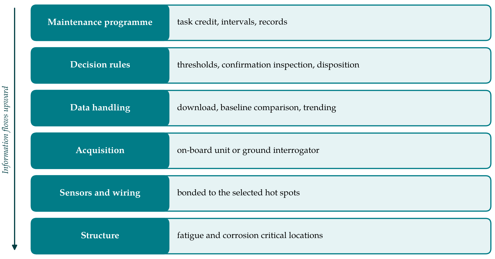
A sensor on an aircraft is airborne equipment. Its adhesive, wiring, connectors and any on-board electronics must survive temperature cycling, vibration, fluids and humidity, and must not themselves create a hazard or initiate corrosion or fatigue at the point of attachment. The established environmental test standard for airborne equipment applies (RTCA, 2010). Durability of the bond is critical, because a sensor that detaches gives either a false alarm or, worse, silence. Self-diagnosis of the sensor and its bond should be a design requirement. The architecture should be decided in layers, as shown in Figure 1, and for a small fleet the lightest option is usually sensors and wiring terminated at an accessible connector that is interrogated on the ground with a portable unit.
3.5. Step 5: Demonstrate detection capability
Credit for an inspection rests on a demonstrated probability of detection for a given crack size. For conventional non-destructive inspection the procedure is codified (DoD, 2009), and it assumes many independent inspections of many flaws by different inspectors. A fixed sensor differs in ways that matter statistically. It occupies one position relative to the flaw, its readings over time are correlated, and variability comes from installation, ageing and environment and not from the human operator. The plan should therefore specify coupon and element tests with representative geometry, sealant, paint and loading, with cracks grown under the sensor, and should state in advance how repeated measurements will be treated. Environmental compensation of the baseline must be shown to work over the temperature and load range expected at the time of reading (Worden et al., 2007).
3.6. Step 6: Agree the route to maintenance credit
With capability evidence in hand, the operator and design approval holder propose the change to the maintenance programme. The conservative route is scheduled monitoring at the existing interval, with the sensor reading replacing the access and the inspection. Any indication is confirmed by conventional means before a disposition is made. Interval extension or fully automated monitoring should be deferred until service experience exists. The damage tolerance justification must be revisited, since the detectable crack size of the sensor, not that of the inspection it replaces, now sets the starting point of the crack growth calculation (Schijve, 2009).
3.7. Step 7: Run a parallel trial on part of the fleet
Before any task is dropped, the system should be flown on a subset of aircraft while the existing inspections continue unchanged. The trial has three aims: to measure the false-call rate in service, to find installation and durability problems, and to exercise the data path from download to engineering disposition. Aircraft should be chosen to span the fleet's age and operating bases. The length of the trial should be fixed in advance in terms of flight cycles and scheduled inspection opportunities, and the criteria for success written down before it begins.
Every disagreement between sensor and inspection during the trial is valuable and should be investigated to a root cause, whether a sensor indication with no crack found or the reverse. Indications without damage usually trace to bond degradation, connector faults or uncompensated temperature, and each cause has a different remedy. Maintenance staff should be trained on the interrogation procedure before the trial starts, so that handling errors are not mistaken for shortcomings of the system.
3.8. Step 8: Review and decide on wider adoption
The final step compares what the trial showed with the objective of the first step. The technical review asks whether the sensors agreed with the conventional inspections and survived. The economic review sets installation, added weight, data handling and continuing airworthiness of the system against the access hours and downtime saved. The balance depends heavily on how often the replaced task recurs and how much access it needs, and it should not be assumed to be favourable. A location that is inspected rarely, or reached easily, will seldom repay a permanent installation.
4. Fitting the Framework to a Small Operator
Three adjustments make the framework workable for a regional carrier. Scope should be kept to a handful of locations in the first instance, chosen for the clearest saving. Development and capability testing should be shared, through the type certificate holder or an operator group, because no single small fleet can fund a probability of detection programme. Data handling should be modest: a pass-or-refer indication recorded in the existing maintenance information system is more useful than a stream of waveforms nobody is resourced to interpret. Statistical methods for novelty detection are well developed (Farrar and Worden, 2013), but for a first retrofit a simple threshold with a confirmation inspection is easier to justify and to audit.
5. Limitations and What Remains to Be Shown
The framework is a proposal and has not been tested on a fleet. Whether its eight steps are sufficient, and whether their order is the most efficient, can be judged only by applying them. A first application would need to show that the parallel trial yields enough inspection opportunities, on a small fleet and within an acceptable time, to support a decision; that the sensor installations last between heavy checks; and that the saving survives contact with real access times. The framework also assumes cooperation from a design approval holder, which for older types with limited manufacturer support cannot be taken for granted. It addresses metallic and bonded structure with known hot spots, and does not claim to cover impact damage to composite airframes or wholly unanticipated damage.
6. Conclusion
A structural health monitoring retrofit is best treated as a change to a maintenance programme that happens to involve sensors, and not as a sensor project in search of a use. The framework proposed here starts from the operator's own inspection burden, narrows to locations where a fixed sensor has a clear task, and builds evidence in stages: qualification, detection capability, agreed credit and a parallel trial. Each stage produces a record that the next depends on. Its practical worth for an ageing turboprop fleet remains to be demonstrated by use.
Conflict of interest
To be declared by the author(s) before publication.
Funding
To be declared by the author(s) before publication.