1. Introduction
Lattice structures built from repeating strut-based or sheet-based cells have moved from laboratory curiosities to load-bearing parts largely because of laser and electron beam powder bed fusion. In Ti-6Al-4V they are used in orthopaedic implants, where an open, porous architecture lowers stiffness towards that of bone and gives tissue somewhere to grow, and in aerospace brackets and panels, where the attraction is stiffness per unit mass (Zadpoor, 2019). The scaling of stiffness and strength with relative density is well described by the cellular solids framework of Gibson and Ashby (1997). Fatigue is less tidy. Implants see millions of gait cycles and airframe parts see vibration and gust loading, and reviews of the field agree that fatigue resistance is the property that most often limits what a lattice can be trusted to do (Benedetti et al., 2021).
The usual tools of fatigue assessment were developed for solid sections with one dominant crack. A stress-life curve needs a nominal stress, and in a lattice the stress that matters is local to a node or to a notch left by a partly fused powder particle. A crack growth law of the type proposed by Paris and Erdogan (1963) needs a crack long enough for a stress intensity factor to be meaningful, whereas a crack in a strut a few hundred micrometres across is short for nearly all of its life. Failure of the structure comes from the progressive loss of struts, each of which has gone through its own initiation and growth, and the order in which struts fail redistributes load onto the rest.
Phase-field models of fracture are attractive in this setting because they do not require the analyst to say in advance where cracks are or how many there will be. The crack is represented by a continuous field that evolves so as to lower the total energy of the body, and initiation, growth, branching and merging all follow from one set of equations. Fatigue extensions of these models are a recent development. This article reviews them with one application in mind, additively manufactured titanium lattices, and asks what stands between the published models and a usable prediction of lattice fatigue life.
2. Scope and Approach
This is a narrative review of the published literature. It draws on the foundational papers of variational fracture, on the phase-field fatigue models that have been most widely taken up, and on experimental and review papers concerning the fatigue of titanium made by powder bed fusion in bulk and lattice form. No claim is made to exhaustive coverage, and no new computations or tests are reported. The emphasis is on small-strain, high-cycle conditions in Ti-6Al-4V, since that alloy accounts for most of the lattice fatigue data in print. Polymer and ceramic lattices, creep-fatigue interaction and corrosion fatigue in body fluids are left aside, although the last is plainly relevant to implants.
3. Fatigue of Additively Manufactured Titanium Lattices
Bulk Ti-6Al-4V made by laser powder bed fusion has a fine acicular martensitic microstructure, high static strength and limited ductility in the as-built state, together with residual stresses from the steep thermal gradients of the process (Lewandowski and Seifi, 2016). Its fatigue strength with the as-built surface is well below that of wrought material, a deficit attributed to surface roughness, porosity and residual stress acting together (Edwards and Ramulu, 2014). Leuders et al. (2013) showed that hot isostatic pressing, by closing internal pores, raises fatigue resistance substantially, and that residual stress has a marked effect on crack growth. These findings carry over to lattices with one aggravating difference: a strut cannot be machined, so its surface remains as built.
3.1. Where cracks start
In a lattice strut the ratio of surface to volume is high, and the surface is covered with adhered powder particles and the stair-step profile of the layers. Fractographic studies of failed lattices place initiation sites at these surface notches, at sub-surface lack-of-fusion or gas pores, and at the fillets where struts meet (Benedetti et al., 2021). The printed geometry also departs from the design: struts are wavy, their cross-section varies along the length, and inclined or horizontal struts carry excess material on the downward-facing side, deviations that Liu et al. (2017) measured by tomography and showed to alter stiffness and failure. For small defects of this kind, Murakami (2002) established that the fatigue limit depends on defect size, expressed through the square root of the projected area, and on hardness, which gives a rational basis for treating pores and notches as small cracks.
3.2. What the cell architecture contributes
Topology decides how the applied load is carried. In bending-dominated cells such as the diamond or the body-centred cubic unit, struts flex and the peak stress sits at the nodes; in stretching-dominated cells such as the octet truss, struts carry mainly axial load (Deshpande et al., 2001). Compression-compression tests on porous Ti-6Al-4V showed that when the applied stress is normalised by the yield stress of the structure, the stress-life data for different porosities fall close to a single curve (Amin Yavari et al., 2013), and later work found that this normalised behaviour still differs between unit cell types and between materials (Ahmadi et al., 2018). The practical lesson is that an empirical curve belongs to one cell, one process and one post-treatment. A model that could carry information from one architecture to another would save a great deal of testing, and this is the role in which phase-field methods are being considered.
4. Phase-Field Fracture in Brief
The starting point is the energy balance of Griffith: a crack advances when the elastic energy released pays for the new surface. Francfort and Marigo (1998) recast this as a minimisation problem in which the displacement field and the crack set are both unknowns, which removed the need for a pre-existing crack and a prescribed path. The problem became computable when Bourdin et al. (2000) replaced the sharp crack by a scalar field varying smoothly between intact and broken material over a width set by a length parameter. Minimising the regularised energy with respect to displacement and damage in turn gives a pair of coupled field equations that standard finite element codes can solve.
Several developments made the approach usable for engineering problems. Miehe et al. (2010a) introduced a history field that enforces irreversibility and permits a robust staggered solution, and the companion paper (Miehe et al., 2010b) set the model in a thermodynamically consistent form with a split of the strain energy into tensile and compressive parts, so that cracks do not grow or interpenetrate under compression. A comparison of this spectral split with the alternative volumetric-deviatoric split, together with a hybrid scheme that keeps the elastic problem linear, is given by Ambati et al. (2015). The choice of split matters for lattices loaded in compression, where struts bend and one side of each strut is in tension while the other is not.
The length parameter deserves particular attention. In the original setting it is a numerical device that should tend to zero. Tanné et al. (2018) showed that, read as a gradient damage model, the formulation with a finite length predicts a critical stress for crack nucleation in an unnotched body, so that the length can be chosen from the tensile strength and toughness of the material and then acts as a material property. The alternative offered by Wu (2017) embeds a cohesive law so that the global response is largely insensitive to the length. For a strut whose diameter is only a modest multiple of any plausible internal length, which of these readings is adopted is not a detail.
5. Extending the Phase Field to Cyclic Loading
A phase-field model driven only by the current elastic energy does nothing under repeated loading below the monotonic threshold. Fatigue requires a mechanism by which cycles that are individually harmless accumulate. The published models differ mainly in where that mechanism is placed, and Table 1 groups them accordingly.
| Route | How cyclic damage enters | Representative source | Point to watch for lattices |
|---|---|---|---|
| One-dimensional precursor | Dissipation falls as accumulated strain grows | Alessi et al., 2018 | Shows the mechanism; not a structural model |
| Toughness degradation | Toughness reduced by a function of accumulated energy history | Carrara et al., 2020 | Compression and load-ratio response depend on the energy split |
| Modified evolution law | Rate term and cyclic damage variable added | Lo et al., 2019 | Calibrated to long-crack growth, not initiation |
| Local strain approach | Toughness reduced by a lifetime variable from strain-life data | Seiler et al., 2020 | Uses standard fatigue data; strut-scale data are scarce |
| Solver acceleration | No new physics: quasi-Newton monolithic solution | Kristensen and Martínez-Pañeda, 2020 | Lowers cost per cycle, not the number of cycles |
The most widely adopted route degrades the fracture toughness. Alessi et al. (2018) introduced, in one dimension, a dissipation that decreases as a measure of accumulated strain grows, and Carrara et al. (2020) generalised the idea to a framework in which the toughness is multiplied by a fatigue degradation function of a history variable that sums the loading increments of the strain energy. Without further assumptions the model reproduces the regimes of a crack growth rate curve, including a Paris-type power law, and stress-life curves for unnotched bodies. Its attraction is economy: a single additional function carries the whole of the cyclic behaviour.
Other authors alter the evolution law or the source of the degradation. Lo et al. (2019) added a rate-dependent term and a cyclic damage variable to a standard formulation and showed that it reproduces Paris-law growth, including for three-dimensional crack fronts. Seiler et al. (2020) took an engineering view: the toughness is reduced according to a local lifetime variable computed with the local strain approach from cyclic stress-strain and strain-life curves, which brings plasticity in without resolving it and uses material data that fatigue laboratories already produce.
All of these share one difficulty. High-cycle fatigue means hundreds of thousands to millions of cycles, and resolving each cycle with several load increments on a mesh fine enough for the length parameter is far beyond routine computation for anything larger than a coupon. Two kinds of remedy have been proposed. One improves the solver: Kristensen and Martínez-Pañeda (2020) showed that quasi-Newton monolithic schemes with adaptive stepping cut the cost of phase-field analyses, fatigue included, sharply in comparison with staggered iteration. The other skips cycles: the damage state is extrapolated over blocks of cycles between fully resolved ones, and the local lifetime variable of Seiler and co-workers serves a similar purpose because it can be advanced in large cycle increments.
6. Bringing the Model to the Lattice
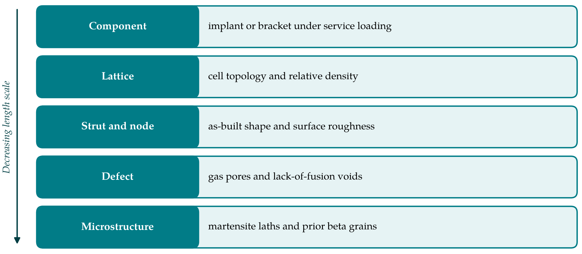
Applying any of these models to a printed lattice means supplying information at several length scales, sketched in Figure 1. Each layer of the figure has its own source of data and its own uncertainty, and a prediction is only as good as the weakest of them.
6.1. Geometry and defects
A model built on the designed geometry, with smooth cylindrical struts, omits the features from which fatigue cracks are known to start. The alternatives are to mesh the as-built geometry directly from computed tomography, which captures waviness, thickness variation and the larger pores but is limited by scan resolution and yields very large meshes, or to idealise the struts and represent roughness and porosity statistically, for instance by a spatially varying toughness or by seeded defects sized from the measured population. The first route is faithful to one specimen; the second can describe scatter across a batch. Because the phase-field length regularises sharp features, surface notches smaller than that length are smeared, and their effect must then be carried by the material parameters and not by the mesh.
6.2. Material parameters and residual stress
The parameters of a fatigue phase-field model are the elastic constants, the toughness, the length and whatever constants enter the fatigue degradation law. In practice they are identified from crack growth and stress-life data on bulk specimens. For printed Ti-6Al-4V those data depend on build orientation, heat treatment and hot isostatic pressing (Lewandowski and Seifi, 2016), and a thin strut solidifies and cools differently from a thick block, so that bulk values may not describe strut material. Residual stress can be entered as an initial stress or eigenstrain field, but it is seldom measured inside lattices. Stress relief and hot isostatic pressing, which are routine for implants, reduce this uncertainty and also coarsen the microstructure, which changes the parameters again (Leuders et al., 2013).
6.3. Scale and cost
A lattice component contains thousands of struts, each needing several elements across the phase-field length. Full resolution of a component over its fatigue life is not feasible at present. The workable strategies are hierarchical. A unit cell or a small cluster of cells is analysed with periodic or representative boundary conditions to obtain the number of cycles to first strut failure and the subsequent loss of stiffness; that response then informs a homogenised or beam-based model of the component. Whether crack patterns computed in a periodic cell represent those in a finite lattice with free surfaces, where failure often localises into a band, is an open question. Beam-element phase-field formulations would lower the cost further but give up the node and surface detail that governs initiation.
7. Gaps and Directions for Further Work
Four gaps stand out. The first is calibration at the right scale. Fatigue tests on single printed struts and small node specimens, with tomography before and after, would allow parameters to be identified on material that has the thermal history and surface of a lattice. The second is validation against more than a life. Agreement with a stress-life curve can be reached by tuning; agreement with the observed sequence and location of strut failures, followed by interrupted tomography, is a much stricter test and has rarely been attempted.
The third gap concerns mean stress, compression and short cracks. Most lattice fatigue data are compression-compression, a regime in which the energy split controls everything and in which crack closure and local plasticity at notches are active. The fatigue degradation functions in common use were shaped on tension-dominated benchmarks, and their handling of load ratio remains under discussion. Microstructurally short cracks, which interact with the martensitic laths and prior beta grain boundaries, lie below the resolution of a continuum toughness. The fourth is scatter. Fatigue lives of nominally identical lattices vary widely, and a deterministic simulation of one geometry says nothing about the distribution. Coupling phase-field analyses to measured defect statistics, in the spirit of the defect-size approach of Murakami (2002), is a natural next step.
Benchmarks would help the field as a whole. The phase-field community has standard monotonic test problems but no agreed fatigue benchmark for architected materials. A shared data set comprising scans, material data and strut-by-strut failure records for one or two cell types would let competing formulations be compared on equal terms, and would show whether the differences between them matter at the scale of a lattice or are swamped by uncertainty in geometry and defects.
8. Conclusion
Phase-field fracture has reached the point where fatigue crack initiation and growth can be simulated in a single variational setting, and several formulations reproduce the standard stress-life and crack growth behaviour of metals. Titanium lattices made by powder bed fusion are a demanding test for them, since life is governed by as-built surfaces, pores and nodes at a scale close to the regularisation length, under loading that is largely compressive. The literature reviewed here suggests that the models are ahead of the data needed to feed them. Strut-scale calibration, validation against observed failure sequences, and a statistical treatment of defects are the steps most likely to turn a promising method into a predictive one.
Conflict of interest
To be declared by the author(s) before publication.
Funding
To be declared by the author(s) before publication.