1. Introduction
Placement decides where every standard cell and macro sits; routing then has to connect them within a fixed supply of tracks and vias. When demand for tracks in a region exceeds supply the router detours, and when detours run out it leaves design rule violations that someone must repair by hand or by re-placing the block. Placement tools therefore try to anticipate congestion, but they do so with fast estimates, since running the router inside every placement iteration is too slow (Kahng et al., 2011). The gap between the estimate and the routed outcome is the source of wasted iterations.
In a mixed-signal chip the digital logic shares the die with data converters, phase-locked loops, regulators, references and radio-frequency blocks. These are laid out under rules of matching, symmetry and isolation that have no counterpart in digital design (Lienig and Scheible, 2020), and they shape the digital placement region from outside. Analog macros block several metal layers, sensitive nets are shielded and take neighbouring tracks, and noisy digital cells are kept away from quiet circuits. The result is a routing resource map with holes and channels that standard congestion estimators, tuned on rectangular digital blocks, represent crudely.
Over the past decade a body of work has shown that machine learning models can predict routed congestion from features of a placement (Kahng, 2018; Huang et al., 2021). This article proposes a way to use such a predictor inside the placement of the digital portion of a mixed-signal design, with the analog-driven constraints supplied to the model as inputs. The procedure is assembled from published methods. It is offered as a design for a flow and has not been applied to a chip or validated here.
2. Background
Three lines of earlier work are combined in the proposal: analytical placement, congestion estimation and its learned successors, and the automation of analog and mixed-signal layout.
2.1. Analytical placement and routability
Modern global placers treat placement as continuous optimisation. In the electrostatic formulation of ePlace, cells are charges, the density constraint becomes a potential energy computed with a fast Fourier transform, and wirelength is minimised by Nesterov's method (Lu et al., 2015). RePlAce refined the approach and added a routability mode in which cells in regions of predicted congestion are inflated, so that the density force spreads them apart (Cheng et al., 2019). DREAMPlace recast the same computation in a deep learning framework to run on graphics processors (Lin et al., 2019). Cell inflation is the lever the proposed flow uses, because it is already present in open tools and needs only a congestion map to drive it.
2.2. Estimating and predicting congestion
The classical estimate spreads the expected wire of each net uniformly over its bounding box and sums the contributions per tile, the measure introduced as RUDY by Spindler and Johannes (2007). It is cheap and ignores blockages, layer assignment and pin access. Learned models take such estimates as inputs and are trained on what a router actually produced. Chan et al. (2016) predicted routability from placement features with attention to the metal stack. RouteNet treated the placement as an image and used a convolutional network to predict both an overall violation count and the location of hotspots, with macros represented explicitly (Xie et al., 2018). CongestionNet instead used a graph neural network on the netlist, so that a prediction is available before placement (Kirby et al., 2019).
2.3. Mixed-signal layout automation
Analog layout has resisted automation for reasons reviewed by Rutenbar et al. (2007): performance depends on parasitics and matching in ways that are hard to state as constraints. Recent open generators, ALIGN (Kunal et al., 2019) and MAGICAL (Xu et al., 2019), extract such constraints from the netlist and produce analog layouts automatically. They handle the analog blocks themselves. The interaction between finished analog blocks and the surrounding digital placement, which is the subject here, has received less attention.
3. The Proposed Flow
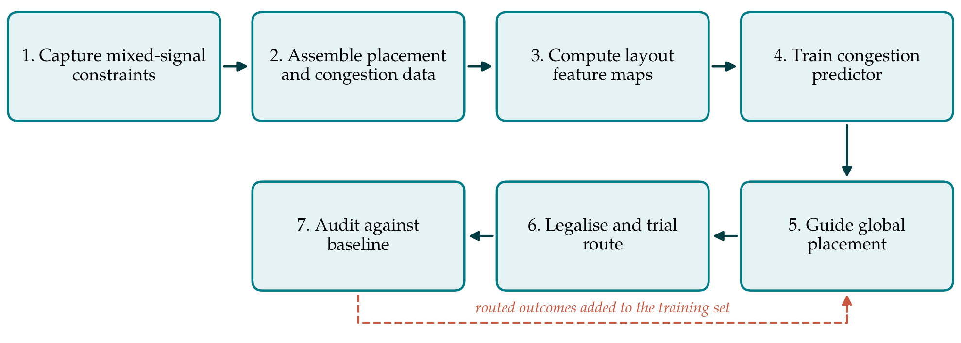
The flow has seven steps, listed in Table 1 with the inputs each consumes and the output it hands on. Figure 1 shows the sequence and the return path by which routed results enlarge the training set. The flow assumes that the analog macros have been laid out and positioned by the floorplan, and that the task is to place the digital standard cells and any digital macros around them.
| Step | Inputs | Output |
|---|---|---|
| 1. Capture constraints | Floorplan, analog macro abstracts, shielding and keep-out rules | Per-layer blockage and capacity maps |
| 2. Assemble data | Earlier placements of comparable blocks and their routing results | Paired placement and congestion samples |
| 3. Compute features | Placement, netlist, capacity maps | Stack of per-tile feature maps |
| 4. Train predictor | Feature stacks and routed congestion labels | Model with held-out error report |
| 5. Guide placement | Intermediate placement, trained model | Inflation factors and density targets |
| 6. Legalise and trial route | Global placement | Routed congestion map, overflow figures |
| 7. Audit | Flow result and baseline result | Comparison record; new training samples |
3.1. Step 1: Capture the mixed-signal constraints as maps
The first step turns the analog-driven restrictions into data a model can read. For each routing layer the die is divided into the tiles of the global routing grid, and the available track capacity of each tile is computed after subtracting macro obstructions, power straps, shield wires and the tracks reserved beside sensitive nets. Placement keep-out regions, guard rings and the zones where only quiet cells are permitted are recorded as separate maps. The work is deterministic and uses information already present in the floorplan and the macro abstracts. Its value is that restrictions usually held in a designer's head or a script become explicit inputs.
3.2. Step 2: Assemble training data
A supervised predictor needs placements paired with the congestion a router produced for them. The natural source is the design team's own history: earlier versions of the block, sibling blocks on the same process, and deliberately perturbed placements generated by varying density targets and seeds. Each is routed with the global router that will be used in production, and the per-tile overflow is stored as the label. Publicly released routability datasets can be used for pre-training, with the caveat that they contain digital designs on a different process and no analog obstructions. Labels must come from one router version and one set of settings, since a change of router alters what the model is asked to learn.
3.3. Step 3: Compute feature maps
For each sample a stack of maps on the routing grid is computed: cell density, pin density, the RUDY estimate of wire demand, the count of nets whose bounding box crosses the tile, and the capacity and keep-out maps from the first step. Capacity is given per layer, or grouped into lower and upper layers, because an analog macro that blocks the lower metals leaves a different resource from one that blocks the whole stack. Features should be normalised by quantities with physical meaning, such as tracks per tile, so that a model trained on one block size remains usable on another.
3.4. Step 4: Train the predictor
The proposed model is a fully convolutional network of the encoder and decoder form introduced by Ronneberger et al. (2015), which maps the feature stack to a congestion map of the same size and has been the usual choice for image-like routability prediction since RouteNet. A graph network over the netlist, as in CongestionNet, is an alternative where predictions are wanted before any placement exists. Whatever the architecture, the held-out set must consist of whole designs or whole floorplans that the model has not seen. Splitting tiles of one placement between training and test sets gives a flattering and meaningless score.
3.5. Step 5: Guide global placement
During analytical global placement the predictor is called at intervals once the cells have spread enough for a density map to be meaningful. Its output is converted into two controls. Cells in tiles with predicted overflow are inflated in proportion to the predicted excess, and the target density of those tiles is lowered. The placer then continues, and the density force moves cells out of the affected regions. Inflation is capped per round and in total, so that the block cannot grow beyond its area budget, and the keep-out maps are enforced as hard constraints throughout. Because the predictor is differentiable, its output could also be added to the objective as a penalty term; the inflation route is proposed first because it leaves the placer's convergence behaviour unchanged.
3.6. Step 6: Legalise and trial route
The global placement is legalised, detail placed and passed to the global router. The routed congestion map is the ground truth against which the prediction is judged for this design, and the overflow figures decide whether the block proceeds to detailed routing or returns to step 5 with adjusted limits. The flow never accepts the model's forecast in place of a routing run. The model's role is to make the first routing run more likely to succeed.
3.7. Step 7: Audit against a baseline
The same block is also placed with the placer's built-in routability mode, and the two results are compared on routed overflow, wirelength, timing and, where analog blocks are sensitive to their surroundings, the checks the analog designers require. The comparison is recorded, and the new placement and its routed map join the training set. Over successive projects the predictor is thereby exposed to the team's own floorplans, which is where a learned model has most to offer.
4. Fitting the Flow to Practice
The flow can be built from open components. OpenROAD provides global placement with cell inflation, a global router and scripting access to both (Ajayi et al., 2019), and the predictor can be trained with any standard framework. In a commercial environment the same structure applies with the vendor's placer and router, provided intermediate placements can be exported and inflation factors read back. Teams with little routing history should begin with step 1 alone: supplying accurate capacity maps to a conventional estimator may recover much of the benefit, and it provides the baseline against which a learned predictor has to justify its added complexity.
5. Limitations and What Remains to Be Shown
The flow is proposed and untested, and its premise could fail in several ways. Mixed-signal floorplans differ greatly from one chip to the next, and a model trained on a few of them may not transfer; the size of training set needed is unknown. Global routing overflow is itself only a proxy for the violations left after detailed routing. The assessment of learning-based macro placement by Cheng et al. (2023), which re-examined the method of Mirhoseini et al. (2021), is a reminder that reported gains in this field depend heavily on the strength of the baseline and on whether the comparison can be reproduced.
An evaluation should therefore establish, on designs withheld from training, that the guided flow reduces routed overflow and post-route violations relative to a well-tuned conventional flow, that it does so without unacceptable cost in wirelength or timing, that the improvement survives a change of floorplan, and that it exceeds what explicit capacity maps achieve without learning. Separately, the effect on the analog blocks, through coupling from digital wires routed nearer or farther than before, has to be checked by the analog designers and cannot be inferred from congestion figures.
6. Conclusion
Congestion in the digital region of a mixed-signal chip is shaped by analog blocks that ordinary estimators see poorly. The flow proposed here makes those restrictions explicit, trains a predictor on the team's own routed placements, and uses it to steer analytical placement through cell inflation while keeping the router as the arbiter. Each element has precedent in the literature; their combination for mixed-signal designs has not been demonstrated, and the article has stated the tests it would have to pass.
Conflict of interest
To be declared by the author(s) before publication.
Funding
To be declared by the author(s) before publication.