1. Introduction
The attraction of millimetre-wave bands is bandwidth. The frequencies between roughly 24 and 71 GHz that fifth-generation New Radio and the 60 GHz wireless local area network standards have opened carry channels far wider than anything available below 6 GHz, and early measurement campaigns established that cellular operation at these frequencies was feasible with directional antennas (Rappaport et al., 2013; Rangan et al., 2014). The price is paid in propagation. Free-space loss for a fixed antenna aperture is manageable with beamforming, but penetration through walls is poor, diffraction is weak, and a link that works well with a clear path can fail when someone walks through it.
Indoors, this produces a coverage map with sharp edges. A ceiling-mounted access point serves an open office well and leaves the corridor round the corner, the meeting room behind a partition, or the far side of a pillar in shadow. The conventional remedies are more access points, each needing power and backhaul, or active relays. A third option has attracted a large literature since about 2019: a reconfigurable intelligent surface (RIS), also called an intelligent reflecting surface, which is a planar array of sub-wavelength elements whose reflection phase can be set electronically so that the reflected wave adds coherently in a wanted direction (Wu and Zhang, 2019; Basar et al., 2019; Di Renzo et al., 2020).
A surface has no power amplifier and regenerates nothing. Everything it delivers comes from the geometry of two hops, access point to surface and surface to user, and from the size of the panel. That makes its position unusually consequential. A relay placed badly still amplifies; a surface placed badly may contribute less than the plasterboard it is fixed to. This article reviews the published work on where an RIS should be put to extend indoor millimetre-wave coverage, and on how that question has been modelled.
2. Scope and Approach
This is a narrative review of the published literature. It draws on the tutorial and survey papers that have organised the RIS field, on the path-loss derivations and measurement reports that underpin link budgets, on studies that treat deployment or placement explicitly, and on the older body of indoor millimetre-wave channel measurements. No claim of exhaustive coverage is made. The emphasis is on results that bear on a practical decision, namely which wall or ceiling position a panel should occupy in a given floor plan, and on the assumptions under which those results hold. Work on outdoor cellular deployment is cited where its reasoning carries over to rooms and corridors.
3. The Indoor Coverage Problem at Millimetre Wavelengths
Wideband measurements in office buildings at 28 and 73 GHz showed two regimes. Where transmitter and receiver see each other, path loss follows something close to free space and may be slightly better because of guiding along corridors. Where they do not, loss rises steeply with distance and varies widely from one location to the next, since the link then depends on whichever reflections happen to exist (MacCartney et al., 2015). The standard channel model used for system evaluation reflects the same split by assigning each link a line-of-sight probability that falls with distance and by applying separate loss formulas to the two states (3GPP, 2020).
Two kinds of obstruction matter. Fixed ones, such as internal walls, lift shafts and metal cabinets, create permanent shadows whose shape can be read from the floor plan. Moving ones, chiefly human bodies, create intermittent outages that last for the fraction of a second or the several seconds that a person takes to cross the beam, with an attenuation of tens of decibels. Analyses of millimetre-wave networks with random blockages show that coverage is governed far more by the probability of having an unobstructed path than by transmit power (Bai and Heath, 2015). The task given to a surface is therefore specific: to supply a second, controllable path with clear sight at both ends to places and moments in which the direct path is closed.
4. How a Surface Redirects Energy
The physical basis is the generalised law of reflection: a phase gradient imposed along an interface steers the reflected wave away from the specular direction (Yu et al., 2011). Programmable metasurfaces realise that gradient with elements switched by PIN diodes or tuned by varactors under digital control (Cui et al., 2014), and the idea of treating walls coated with such material as part of the network followed. Three properties of the resulting link shape every placement result in the literature.
4.1. Product-distance path loss
When both the access point and the user are in the far field of the panel, the surface behaves as a collection of scatterers and not as a mirror. The received power is then proportional to the square of the number of elements and inversely proportional to the product of the squared distances of the two hops. This was derived from physical optics by Özdogan et al. (2020) and confirmed in anechoic chamber measurements with fabricated panels by Tang et al. (2021), who also gave separate formulas for far-field beamforming, near-field beamforming and near-field broadcasting. The quadratic growth with element count is the array gain of coherent combining collected twice, once on capture and once on re-radiation (Wu and Zhang, 2019).
The product form has a direct geometric consequence. For a surface constrained to a wall that runs parallel to the line joining the access point and the user, the product of the two distances is largest near the midpoint and smallest near either end. A specular reflector, whose loss depends on the sum of the distances, would be indifferent to where along that line it sat. An RIS in the far field is not.
4.2. Near field and aperture size
The far-field assumption is often violated indoors. The Fraunhofer distance of an aperture of largest dimension D is 2D2/λ. At 28 GHz the wavelength is about 1.07 cm, so a panel half a metre across has a far field that begins roughly 47 m away, which is longer than most rooms. Users and access points within that range see a surface that must focus energy on a point and not merely steer a beam, and the simple product-distance law overstates the loss. In the limit of a very large panel close to both terminals the surface approaches mirror-like behaviour, with the gain saturating instead of growing without bound (Tang et al., 2021; Wu et al., 2021). Placement rules derived under far-field models should be read with that limit in mind.
4.3. Hardware limits
Real elements do not offer a continuous phase. Analysis of discrete phase shifters shows that one-bit control costs a few decibels of received power relative to ideal phases while two bits recover most of the loss, which is why low-resolution designs dominate prototypes (Wu and Zhang, 2020). The element response also weakens at oblique incidence, so a panel addressed at a grazing angle delivers less than its area suggests. Reported prototypes at sub-6 GHz and millimetre-wave frequencies, including panels with hundreds to thousands of one-bit or two-bit elements, demonstrate useful gains in rooms and corridors and make the angular roll-off visible in practice (Dai et al., 2020; Pei et al., 2021). The panel still needs a low-rate control link and a small power supply, which is a placement constraint of its own.
5. What the Literature Says About Placement
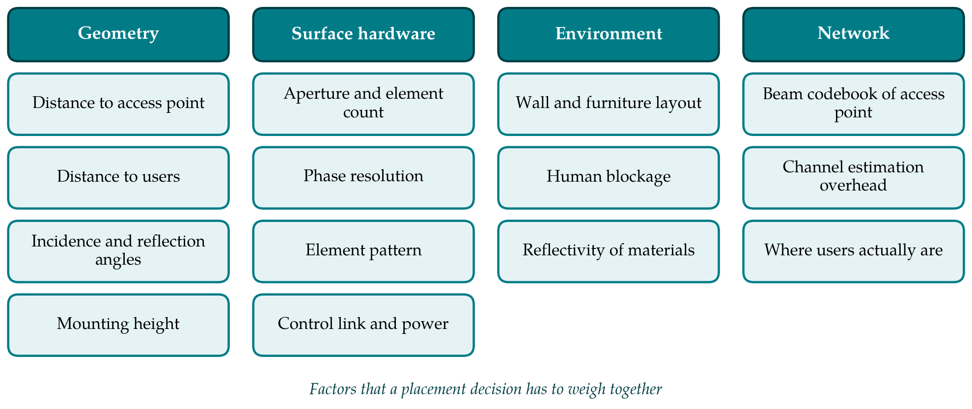
Placement has been studied with tools that range from closed-form link budgets to full electromagnetic simulation of a building. Table 1 compares the main approaches, and Figure 1 groups the factors that they try, with varying completeness, to account for. Four findings recur across them.
| Approach | What is modelled | Strength | Limit |
|---|---|---|---|
| Closed-form link budget | Two-hop path loss for given distances and angles (Tang et al., 2021) | Transparent; gives rules of thumb | Ignores blockage and room geometry |
| Stochastic geometry | Random blockages and randomly sited surfaces (Kishk and Alouini, 2021) | Coverage probability for a whole area | Says little about one specific floor plan |
| Optimisation over candidates | Position and orientation as decision variables (Zeng et al., 2021) | Handles several users and constraints | Result depends on the channel model assumed |
| Ray tracing of the floor plan | Site-specific paths, materials and shadows | Captures the actual building | Needs an accurate model and RIS scattering pattern |
| Prototype measurement | Received power with a fabricated panel (Pei et al., 2021) | Includes real hardware losses | Few positions and one environment at a time |
| Learning-based search | Mapping from layout features to good positions | Fast once trained | Needs training data from one of the other methods |
5.1. Close to one end of the link
The most widely repeated guidance follows from the product-distance law: put the surface near the access point or near the users, not halfway between. Wu et al. (2021) set this out in their tutorial and discuss the trade-off between the two ends. A surface beside the access point enjoys a strong, static first hop and can serve users over a wide angle, but its second hop is as long as the direct path would have been. A surface near the users has a short second hop and helps a small area very effectively. For indoor coverage holes, which are local by nature, the second arrangement usually fits better: the panel is mounted where it overlooks the shadowed region and still sees the access point.
5.2. Line of sight on both hops
At millimetre wavelengths a surface is useful only if both of its hops are unobstructed, because a blocked hop costs more than the panel can recover. The placement problem is thus first a visibility problem: the set of admissible positions is the intersection of the region visible from the access point and the region visible from the target area. In an L-shaped corridor this set is small and obvious, the wall facing the corner. In a furnished open-plan office it is larger and less obvious. The stochastic geometry analysis of Kishk and Alouini (2021), though set outdoors, makes the general point that surfaces mounted on the very objects that cause blockage convert a fraction of blocked links into indirect line-of-sight links, and that the fraction grows with the density of equipped obstacles. Height matters for the same reason, since a panel above head level keeps its sight lines when people move below.
5.3. Orientation as well as position
A panel fixed flat to a wall has its orientation dictated by the wall, and the angles of incidence and reflection then follow from the position. Because element gain falls away from broadside, two candidate positions at equal distances can differ markedly in delivered power. Zeng et al. (2021) treated orientation and horizontal distance as joint variables in a coverage-maximisation problem and showed that the two cannot be chosen independently. In indoor practice the implication is that corner mounts, tilted brackets and ceiling positions deserve consideration alongside flat wall mounting, particularly when the shadowed region lies at a steep angle from the only wall that sees the access point.
5.4. One large panel or several small ones
Since received power grows with the square of the element count on a single panel, concentrating elements maximises the gain towards one region. Splitting the same elements over several walls forfeits part of that gain and buys diversity against blockage, because a person who interrupts one indirect path rarely interrupts all of them. Which matters more depends on whether the outage being addressed is a permanent shadow or an intermittent one. The survey literature treats this centralised versus distributed choice as open and dependent on scenario (Pan et al., 2021; Di Renzo et al., 2020). It also notes a system cost that placement studies tend to leave out: the access point must learn the cascaded channel for every panel, and training overhead grows with the number of elements and panels (Zheng et al., 2022).
6. Interaction With Beamforming at the Access Point
A millimetre-wave access point does not radiate uniformly. It forms narrow beams with a phased array, usually chosen from a codebook by a beam-training procedure, and hybrid analogue and digital architectures limit how many directions can be served at once (Heath et al., 2016). A surface is one more direction to illuminate. When it is placed close to the access point, a single fixed beam can feed it continuously, and all adaptation happens in the panel. When it is far away, the access point must spend a beam on it with correspondingly less array gain to spare elsewhere. Joint designs of the transmit precoder and the surface phases for millimetre-wave channels exploit the fact that the first hop is nearly rank one and can be learned once (Wang et al., 2020). Placement that keeps this first hop static and unobstructed simplifies everything built on top of it.
7. Surfaces Compared With Relays and Additional Access Points
A fair assessment of placement has to ask whether a surface is the right device for the position at all. Björnson et al. (2020) compared an RIS with a decode-and-forward relay and concluded that the surface needs a large number of elements, typically hundreds, before it matches the relay in rate or energy efficiency, because the relay overcomes the product-distance loss by regenerating the signal. The energy-efficiency case for surfaces rests on their very low power draw per element (Huang et al., 2019). Indoors at millimetre wavelengths the comparison is kinder to the surface than at lower frequencies: elements are small, so a panel of modest physical size holds many of them, and distances are short. An extra access point remains the stronger remedy where cabling exists. The surface earns its place on walls that have sight lines and no backhaul. Standardisation work has begun to catalogue such deployment scenarios (ETSI, 2023).
8. Gaps and Directions for Further Work
Several weaknesses run through the placement literature. Much of it assumes far-field propagation and idealised elements, whereas indoor geometry sits largely in the radiating near field and real panels have angle-dependent, quantised responses. Many studies optimise for a single user or a fixed set of users, while a coverage tool has to serve wherever people happen to be. Dynamic human blockage, the main cause of indoor outage, is commonly reduced to a static probability. And the standard system-level channel models do not yet include a surface as a scattering object, which leaves each study to build its own (3GPP, 2020).
Three directions follow. Site-specific planning tools that combine ray tracing with a validated RIS scattering model would let placement be decided from a building drawing in the way access point positions are planned today. Measurement campaigns in furnished, occupied rooms, reporting several panel positions for the same layout, would test the end-of-link and visibility rules where they are meant to apply. Finally, comparisons at equal cost, counting installation, control and channel-estimation overhead, would show when a second panel, a larger panel or a small relay is the better use of the same wall.
9. Conclusion
The literature supports a short list of placement principles for indoor millimetre-wave coverage. A surface should see both the access point and the shadowed region without obstruction, sit close to one end of the link, preferably the user end when the aim is to fill a local hole, face its two hops as near to broadside as the walls allow, and be mounted high enough to stay clear of people. These rules come mainly from analysis and from a limited number of prototype measurements. They are well grounded in the physics of the cascaded channel, but their quantitative reach in furnished, occupied buildings has still to be established by site-specific modelling and measurement.
Conflict of interest
To be declared by the author(s) before publication.
Funding
To be declared by the author(s) before publication.