1. Introduction
Small gantry mills sold for workshops, laboratories and schools share a layout. Two side members carry a cross beam; a carriage with the spindle travels along the beam; and either the beam or the table moves in the third direction. The cutting force enters at the tool tip, well below the beam, and reaches the base through the carriage, the linear guides, the beam and its end supports. In this chain the beam is the longest unsupported member. It bends, and because the tool is offset from its axis it also twists, and both deflections appear directly as error at the workpiece.
The designer of an industrial machine answers this with mass: cast iron, welded steel or mineral casting in generous sections (Mohring et al., 2015). The designer of a desktop machine cannot. The beam often moves, so its mass sets the motor size and the attainable acceleration, and the whole machine has to be shipped and carried. The usual compromise is a rectangular aluminium section chosen by experience. Structural optimisation is seldom used at this scale, although the tools are now widely accessible and the benefits of lightweight moving structures in machine tools are documented (Kroll et al., 2011; Zulaika et al., 2011).
This article proposes a design procedure that brings topology optimisation to the gantry beam of a desktop machining centre. It is a method paper. No beam has been designed, built or measured for it, and no performance figures are claimed. The aim is to set out the steps, the reasoning behind each and the checks that a first application should include.
2. Background
Two bodies of literature meet in this problem: the theory and practice of topology optimisation, and what is known about the static and dynamic behaviour of machine tool structures.
2.1. Topology optimisation in brief
Topology optimisation asks how a fixed amount of material should be distributed within a given volume so that a structural measure is as good as possible. The field began with the homogenisation method of Bendsoe and Kikuchi (1988). The form used in most software is the density approach, in which each finite element carries a density variable between zero and one and intermediate values are penalised so that the solution tends toward solid and void (Bendsoe, 1989). The standard reference is the monograph of Bendsoe and Sigmund (2003), and the compact teaching code published by Sigmund (2001) made the algorithm widely understood.
Several numerical matters have to be handled for the result to mean anything. Without regularisation the solution depends on the mesh and shows checkerboard patterns; filtering of sensitivities or densities imposes a length scale and removes both (Sigmund and Petersson, 1998). The design variables are usually updated by an optimality criteria scheme or by the method of moving asymptotes (Svanberg, 1987). Stiffness problems are posed as minimum compliance under a volume constraint. Dynamic problems maximise a natural frequency, which is harder, because modes switch order during the iterations and low-density regions produce spurious local modes (Pedersen, 2000). A comparative account of the density approach and its alternatives is given by Sigmund and Maute (2013).
The raw output of an optimisation is seldom manufacturable. Restrictions that tie the result to a process, such as a minimum member size, symmetry planes, a constant section along an extrusion direction, or a draw direction for casting and for milling from one side, can be imposed during the optimisation, and their formulations are surveyed by Liu and Ma (2016).
2.2. Machine tool structures
The principles of stiff machine design are long established: short, direct force paths, closed sections for torsion, material placed far from the neutral axis, and attention to joints, which often contribute more compliance than the members they connect (Slocum, 1992). Structural behaviour is predicted today with finite element models coupled to models of drives and control, the approach described as the virtual machine tool (Altintas et al., 2005), and the dynamic compliance at the tool point is known to vary with axis position (Law et al., 2013). That last observation matters for a gantry beam, which is loaded at a different point for every position of the carriage.
3. The Proposed Procedure
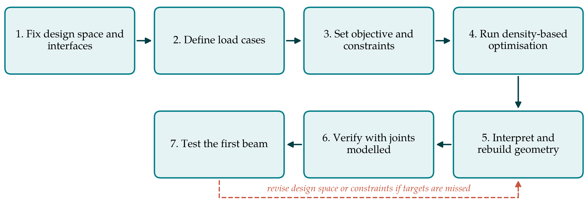
The procedure has seven steps, shown in Figure 1. The first three define the problem and largely decide the quality of the answer; the fourth is the optimisation run itself; the last three turn its output into a part and check it. Each step is described below with the decisions it requires.
3.1. Step 1: Fix the design space and interfaces
The design space is the largest envelope the beam may occupy: the span between the side members, the height available below the top of the machine enclosure, and the depth that still leaves the carriage and spindle within the footprint. Regions that must remain solid are marked as non-design: the mounting faces and bolt bosses for the two linear guide rails, the seats of the ball screw or belt drive, and the end faces that bolt to the side members. Regions that must stay empty, such as cable routes and the travel envelope of the carriage, are excluded. A generous design space gives the optimiser room to find deep sections; the temptation to start from the existing beam should be resisted.
3.2. Step 2: Define the load cases
A beam optimised for one load is poor under any other. The load cases should therefore span the conditions of use, and Table 1 lists a minimal set. Cutting forces are applied at the tool tip and carried to the beam through a rigid or simplified carriage, so that the offset of the tool produces the correct bending and torsion. They are applied in each horizontal direction and vertically, with the carriage at mid-span and near one end. Inertia loads from acceleration of the beam axis and gravity acting on the carriage complete the set. Magnitudes come from the rated spindle power and the cutting parameters the machine is sold for, estimated with a standard cutting force model.
| Load case | How it is applied | Behaviour controlled |
|---|---|---|
| Feed force along the beam | At the tool tip, carriage at mid-span and near one end | Axial path through guides and drive seat |
| Force across the beam | At the tool tip, horizontal and normal to the beam | Horizontal bending and torsion |
| Vertical force | At the tool tip, upward and downward | Vertical bending and torsion |
| Carriage weight | Gravity on carriage and spindle at mid-span | Sag and guide straightness |
| Axis acceleration | Body load on beam and carriage in the travel direction | Racking of the beam on its supports |
| Lowest natural frequency | Modal analysis with carriage mass attached | Dynamic stiffness and servo bandwidth |
3.3. Step 3: Set the objective and constraints
The simplest robust formulation minimises a weighted sum of the compliances of the static load cases subject to an upper limit on mass. The weights express how much each direction matters; equal weights on the two horizontal cutting directions and a smaller weight on gravity are a reasonable starting point. An alternative is to minimise mass subject to limits on tool point displacement in each case, which matches the way a specification is written but converges less readily. A lower bound on the first natural frequency, evaluated with the carriage mass attached, may be added as a constraint. Treating frequency as a constraint and not as the objective avoids most of the mode-switching difficulties described by Pedersen (2000).
3.4. Step 4: Run the optimisation with manufacturing restrictions
The manufacturing route should be chosen before the run, since it determines the restrictions. For a beam milled from aluminium plate on a three-axis machine, a draw direction and a minimum member size no smaller than a practical rib thickness are appropriate. For an extruded profile, the density is constrained to be constant along the span, which reduces the problem to the design of a cross-section. For a sand casting in iron or aluminium, draw directions and a minimum wall are set by the foundry. Symmetry about the mid-span plane is normally imposed. The mesh should be fine enough for several elements across the smallest member, and the filter radius is set from the minimum member size. Running the optimisation at two or three mass limits shows how stiffness trades against weight and where additional material stops paying.
3.5. Step 5: Interpret the result and rebuild the geometry
The density field is a suggestion, not a drawing. The designer reads it for its structural message: where the optimiser has formed a closed torsion box, where it has placed diagonal webs, how it has tied the rail seats to the end supports. This is then redrawn as clean geometry with constant wall thicknesses, fillets and tool access. Thin intermediate-density regions are either made solid or removed. For a small beam the interpretation often resolves into a recognisable form, such as a closed box with diagonal internal ribs and lightening pockets on the faces that carry little load, and this is acceptable: the value of the optimisation lies in showing which of the many possible ribbed boxes is the efficient one.
3.6. Step 6: Verify with the joints modelled
The rebuilt beam is analysed again, this time in the assembly. The linear guide carriages are represented by springs with the stiffness values given in the manufacturer's catalogue, the bolted end joints by contact or by spring elements, and the side members and base are included. The load cases of Table 1 are repeated and the tool point displacements compared with the targets and with the original beam analysed in the same model. A modal analysis gives the lowest natural frequencies and shows whether they are beam modes or rigid-body motion on the guides. Where the model reveals that joints dominate the compliance, further work on the beam is wasted, and the result should be reported as such.
3.7. Step 7: Test the first beam
A design procedure is complete only when its prediction has been checked. Two measurements are proposed for the first beam built. Static stiffness at the tool point is measured by loading the spindle nose against the table through a load cell and reading the relative displacement with an indicator, in the directions of the load cases. Dynamic behaviour is measured by impact testing, with an instrumented hammer and an accelerometer, to obtain the frequency response at the tool point and the lowest mode shapes (Ewins, 2000). Geometric accuracy of the assembled axis is checked by the methods of the machine tool test code (ISO, 2012). The same measurements on the original beam provide the baseline.
4. Fitting the Procedure to a Small Manufacturer
A maker of desktop machines seldom employs a structural analyst, and the procedure is written with that in mind. The optimisation modules built into mainstream design software are adequate for steps 3 and 4, and open educational codes allow the method to be learned on small problems first (Andreassen et al., 2011). Material choice interacts with the method. Aluminium has about one third of the density and one third of the elastic modulus of steel, so the two are close in specific stiffness, and the case for aluminium in a small beam rests on ease of machining and on freedom to use thick, deep sections that resist local buckling. The optimisation does not change that reasoning; it refines the layout within the chosen material. Cost should be assessed on the rebuilt geometry, since pocketing time on a milled beam can outweigh the saving in stock.
5. Limitations and What Remains to Be Shown
The procedure is proposed and has not been validated in this article. Its central assumption, that a compliance-based optimisation under a handful of static load cases yields a beam that also behaves well dynamically, is plausible for a short, stiff member but needs to be checked by measurement. A first application should report the mass and the measured static and dynamic stiffness of the optimised beam against the original, state how far the measurements agree with the model of step 6, and record the time and cost of design and manufacture.
Several effects lie outside the method as described. Damping is not optimised, and a lighter beam with the same stiffness has a higher natural frequency but no more damping, so chatter behaviour may not improve in proportion. Thermal distortion from motor and spindle heat is not considered. Linear static analysis ignores local buckling of thin webs, which the minimum member size guards against only indirectly. Finally, the result is specific to the load weights chosen in step 3, and a manufacturer whose customers cut mainly wood and plastics will reasonably choose differently from one whose customers cut steel.
6. Conclusion
The gantry beam of a desktop machining centre is a good candidate for topology optimisation: a single part, clearly bounded, whose stiffness and mass both matter. The seven steps proposed here place most of the effort in defining the design space, load cases and manufacturing restrictions, and treat the optimisation output as guidance to be interpreted and then verified in an assembly model and on the first beam built. Whether the gain justifies the effort for a given machine is a question that only an application with measurements can settle, and the article has set out what such an application should report.
Conflict of interest
To be declared by the author(s) before publication.
Funding
To be declared by the author(s) before publication.