1. Introduction
Irrigation brings salt with the water. Even canal water of good quality delivers a load that must leave the root zone by leaching if the soil is to stay productive, and leaching requires somewhere for the percolate to go. In many canal commands the natural drainage was never sufficient for the recharge that followed the arrival of irrigation. Seepage from unlined channels and percolation from fields raised the water table year by year until it stood within reach of evaporation from the surface. From that point the profile gains salt during every dry spell, and land that once grew two crops a year begins to show bare patches and white crusts (Smedema et al., 2004).
The economic cost of such degradation is large. Qadir et al. (2014) assembled estimates of the income lost on salt-affected irrigated land and argued that reclamation is usually cheaper than continued inaction. Yet reclamation schemes have a mixed record. Experience from farmers' fields in India shows that subsurface drainage can restore yields on waterlogged saline land, and also that the engineering succeeds only when the organisation, the financing and the maintenance succeed with it (Ritzema et al., 2008).
This article sets out a planning procedure for a command area in which waterlogging, salinity and sodicity occur together, so that drainage and a calcium amendment are both needed. It is addressed to the engineer or soil scientist charged with preparing a restoration plan. The procedure is assembled from standard references and is offered as a proposal; no application to a particular scheme is reported.
2. Background
Three bodies of established knowledge underlie the procedure: the diagnosis of salt-affected soils, the theory of subsurface drainage, and the chemistry of sodic soil reclamation.
2.1. Diagnosing salinity and sodicity
The classification in general use comes from the United States Salinity Laboratory (Richards, 1954). It rests on two measurements: the electrical conductivity of the saturation extract (ECe), which indexes soluble salts, and the exchangeable sodium percentage (ESP), which indexes the sodium held on clay and organic matter. An ECe of 4 dS/m and an ESP of 15 separate the classes, as Table 1 shows. The distinction governs the remedy. Soluble salts are removed by water alone. Exchangeable sodium must first be displaced by calcium, and if it is not, the clay swells and disperses when the salt concentration of the soil solution falls (Quirk and Schofield, 1955; Shainberg and Letey, 1984).
| Class | EC (dS/m) e | ESP | Principal reclamation measure |
|---|---|---|---|
| Normal | Below 4 | Below 15 | Maintain leaching and keep the water table deep |
| Saline | Above 4 | Below 15 | Drainage followed by leaching; no amendment needed |
| Saline-sodic | Above 4 | Above 15 | Drainage, calcium amendment, then leaching |
| Sodic | Below 4 | Above 15 | Calcium amendment with enough water to dissolve and leach it |
| Waterlogged, not yet saline | Below 4 | Below 15 | Drainage to forestall salt accumulation |
2.2. Subsurface drainage
A subsurface drainage system is a grid of perforated pipes laid below the root zone that intercepts groundwater and carries it to a collector and an outlet. Its design turns on the depth at which the water table is to be held and the rate at which water must be removed. Spacing is calculated from the hydraulic conductivity of the soil and the depth to an impermeable layer, using the steady-state equation of Hooghoudt or a non-steady-state equation such as Glover-Dumm, both of which are set out in the standard manual edited by Ritzema (1994). In arid regions the governing criterion is salinity control: the water table must stay deep enough, for long enough, that the net movement of water through the root zone over the year is downward (Smedema et al., 2004).
2.3. Gypsum and the exchange complex
Gypsum, calcium sulphate dihydrate, is the amendment most widely used on sodic soils because it is cheap, safe to handle and soluble enough to supply calcium at a useful rate. Calcium replaces sodium on the exchange sites, and the sodium sulphate formed is leached below the root zone. The dissolving gypsum also keeps the electrolyte concentration of the percolating water high enough to hold clay flocculated while the exchange proceeds (Oster and Frenkel, 1980). The quantity needed can be estimated from the exchangeable sodium to be replaced over a chosen depth, or measured directly with the gypsum requirement test described in the Salinity Laboratory handbook (Richards, 1954). Field practice in several countries is summarised by Abrol et al. (1988).
3. The Proposed Procedure
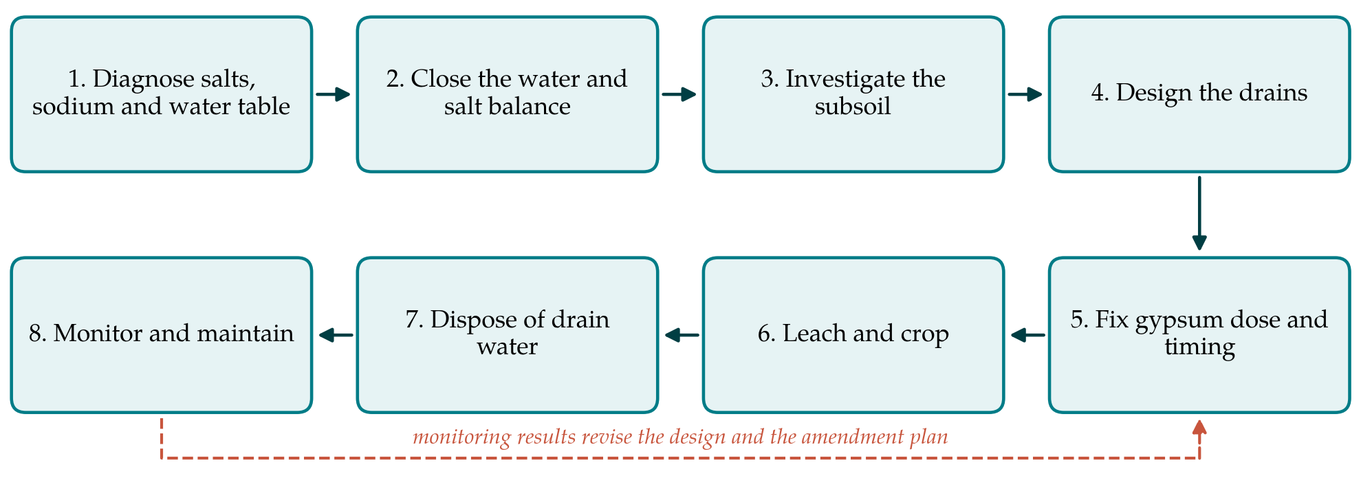
The procedure has eight steps, shown in sequence in Figure 1. The order matters. Each step produces information the next one requires, and the commonest planning errors amount to taking a later step before an earlier one is complete. The steps are described below with the methods on which each relies.
3.1. Step 1: Diagnose salts, sodium and the water table
The first task is to map what is wrong and where. Soil is sampled by depth increments on a grid or along transects and analysed for ECe, pH and ESP or the sodium adsorption ratio of the extract. Because laboratory analysis is slow and salinity varies over short distances, the point samples are best used to calibrate a survey of apparent electrical conductivity made with an electromagnetic induction instrument, which covers ground quickly and reveals the pattern between sampling points (Rhoades et al., 1999; Corwin and Lesch, 2005). A network of observation wells read through at least one full irrigation year records the depth and salinity of the water table. The output is a set of maps that divide the command into the classes of Table 1.
3.2. Step 2: Close the water and salt balance
Drainage treats a symptom unless the sources of recharge are known. A water balance for the affected area sets canal seepage, field percolation, rainfall and lateral inflow against evapotranspiration, natural drainage and pumping. The salt balance multiplies each flow by its concentration. Two results follow. The balance yields the drainage coefficient, the depth of water per day that the system must remove. It also shows whether part of the problem can be removed at source, by lining a leaking distributary or changing irrigation schedules, which reduces the drainage required and the volume of saline effluent to be disposed of (Tanji and Kielen, 2002).
3.3. Step 3: Investigate the subsoil
Drain spacing is sensitive to hydraulic conductivity, and conductivity varies widely within a single soil unit. It should be measured in place below the water table, for which the auger-hole method is the standard technique, at enough points to characterise each unit. Borings establish the depth to any layer of low permeability, and particle size analysis of the soil at drain depth indicates whether pipes will need an envelope of gravel or synthetic fabric to prevent sediment from entering (Ritzema, 1994).
3.4. Step 4: Design the drains
With the drainage coefficient from Step 2 and the soil parameters from Step 3, depth and spacing are calculated, the layout is fitted to field boundaries and the canal network, and collectors and the outlet are sized. Where no gravity outlet exists, a sump and pump are included. The design should be checked against the salinity criterion and not only against the waterlogging criterion. Provision for controlling the outflow, by a weir or valve at the collector, deserves consideration: controlled drainage allows the water table to be held higher when leaching is not needed, which saves irrigation water and reduces effluent (Ayars et al., 2006).
3.5. Step 5: Fix the gypsum dose and its timing
Gypsum is prescribed only for the units classed as sodic or saline-sodic. The dose is computed for the depth of soil to be reclaimed in the first instance, which is commonly less than the full root zone, and adjusted for the purity and fineness of the material available. Timing is the point at which joint planning matters most. On saline-sodic land the amendment must be in place before heavy leaching begins, because washing out the soluble salts while sodium still dominates the exchange complex leaves a dispersed, almost impermeable soil. On the same land, gypsum applied before the drains are working is largely wasted, since the displaced sodium has no exit. The amendment therefore follows drain installation and precedes the main leaching.
3.6. Step 6: Leach and crop
Reclamation leaching is planned as a depth of water to be passed through the profile, applied by ponding or in intermittent irrigations. Once the profile is within the tolerance of a crop, the long-term leaching requirement can be estimated from the salinity of the irrigation water and the salinity the crop tolerates, following Ayers and Westcot (1985), with crop tolerance taken from the threshold and slope values compiled by Maas and Hoffman (1977). Cropping should begin early. A tolerant crop grown during reclamation provides income, its roots open the soil, and the carbon dioxide released in the root zone helps dissolve native calcium carbonate where it is present, a process that can supplement or partly replace the amendment (Qadir et al., 2007).
3.7. Step 7: Dispose of the drain water
Every drainage scheme produces a saline effluent, and a plan that does not say where it goes is incomplete. The options are discharge to a river or main drain where dilution and regulation allow, reuse on tolerant crops or trees, blending with canal water, and evaporation basins. Each has limits that are set by the salt load and by any toxic constituents such as boron. Guidance on reuse is given by Rhoades et al. (1992) and on disposal more generally by Tanji and Kielen (2002).
3.8. Step 8: Monitor and maintain
The observation wells and a subset of the soil sampling points from Step 1 become the monitoring network. Water table depth, drain discharge and effluent salinity are recorded through the year, and soil is resampled at the same season annually. The records show whether the water table and root-zone salinity are moving as intended, and they are the basis for revising gypsum doses, leaching depths or the operation of control structures. Maintenance of outlets, pumps and collectors must be assigned to a named body with a budget.
4. Fitting the Procedure to a Command Area
A command area is a social unit as much as a hydraulic one. Drains cross many holdings, and a lateral that serves ten farmers fails if one of them blocks it. Experience in India indicates that farmers should take part in planning from the start and that responsibility for operation should be agreed before construction (Ritzema et al., 2008). Financial analyses of drainage on salt-affected land in Haryana found the investment worthwhile at farm level (Datta et al., 2000), but the returns arrive over years and smallholders seldom have the capital. Cost sharing and credit arrangements belong in the plan alongside the engineering.
Phasing is the other practical matter. A pilot block of manageable size, representative of the main soil units, allows the design assumptions on conductivity, drain spacing and gypsum dose to be checked before the whole command is committed.
5. Limitations and What Remains to Be Shown
The procedure has not been validated in this article. It is a synthesis of accepted methods arranged in a sequence the author considers sound, and its worth can be judged only by applying it and comparing the outcome with schemes planned differently. Several conditions would call for adaptation. Heavy cracking clays behave unlike the permeable soils for which the drainage equations were derived. Where the groundwater is itself strongly sodic, or the irrigation water has a high sodium adsorption ratio, gypsum may be needed repeatedly instead of once. Where no acceptable outlet for effluent exists, drainage may have to give way to salt-tolerant cropping or tree plantations that lower the water table by transpiration. The gypsum requirement test is known to depart from field behaviour in soils containing soluble carbonates. None of these cases is treated in detail here.
6. Conclusion
Drainage and gypsum address different parts of the same problem, and each depends on the other where salinity and sodicity coincide beneath a high water table. The eight steps proposed here place the two measures in a single sequence: diagnose, balance, investigate, design, amend, leach, dispose, monitor. The sequence asks for nothing that the standard manuals do not already describe. Its contribution is the ordering and the insistence that the amendment plan, the drainage design and the disposal of effluent be decided together. Whether that ordering improves outcomes in practice is a question for pilot projects and their monitoring records.
Conflict of interest
To be declared by the author(s) before publication.
Funding
To be declared by the author(s) before publication.