1. Introduction
Mountain roads are built by cutting into hillsides, and the cuts are commonly formed at the steepest angle that stood during construction. They pass through whatever the hillside happens to contain: colluvium, weathered rock, jointed bedrock and the contacts between them. Most are designed with little ground investigation, and their drainage deteriorates within a few seasons. It is unsurprising that cut slopes account for a large share of the landslides that close such roads during monsoon and typhoon rain (Cruden and Varnes, 1996).
Terzaghi (1950) distinguished long ago between the causes that bring a slope to the verge of failure and the trigger that finally sets it in motion. In a rainfall-triggered failure the trigger is obvious and the causes are not. Whether a slope fails as a shallow slide in soil, a planar slide on a joint or a wash-out below a culvert depends on what the ground is made of and how water moves through it. A remedy matched to the wrong mechanism wastes money and leaves the hazard in place.
This article sets out a procedure for the engineer or engineering geologist called to such a failure. It is addressed to road authorities and their consultants working with modest budgets, and it aims to make sure that the geological control is identified before the remedy is chosen. The procedure is proposed on the basis of published practice. It has not been applied to a specific failure in this article, and no case data are reported.
2. Background
Three bodies of knowledge underlie the procedure: how rain destabilises slopes, how geology determines the form of failure, and how failures are described.
2.1. How rainfall brings a slope to failure
Rain reduces stability by changing pore-water pressure. In a slope above the water table, infiltration reduces matric suction and with it the part of the shear strength that suction provides (Fredlund and Rahardjo, 1993). Where a wetting front meets a less permeable layer, a perched water table can form and positive pressures develop. Iverson (2000) showed how the timing and depth of failure follow from the transient transmission of pore pressure, which depends on rainfall intensity and duration relative to the hydraulic properties of the ground. The response of a slope to a storm is thus governed by rainfall intensity, by the permeability of the soil and by how wet the ground was beforehand.
Empirical thresholds relate landsliding to rainfall intensity and duration. The original global threshold of Caine (1980) was updated with a much larger catalogue by Guzzetti et al. (2008). Thresholds describe when failures become likely across a region. They do not explain why one cut failed and its neighbour stood, and that is a question of geology.
2.2. Geological controls
In rock, the control is usually structural. A cut that daylights a persistent joint, bedding plane or foliation dipping out of the face at an angle steeper than its friction angle is kinematically free to slide, and the same is true of wedges formed by two intersecting sets (Hoek and Bray, 1981; Wyllie and Mah, 2004). In weathered profiles the joints of the parent rock survive as relict discontinuities and play the same part within what appears to be soil. In colluvium and residual soil, failure commonly follows the contact with underlying rock or a change in permeability. Hencher (2010) has drawn attention to preferential flow paths, such as soil pipes, open relict joints and permeable dykes, which deliver water rapidly to particular parts of a slope and account for failures that uniform-infiltration models do not predict.
2.3. Describing the failure
A consistent description is the first product of an investigation. The classification of Varnes (1978), revised by Cruden and Varnes and updated by Hungr et al. (2014), names a landslide by its material and type of movement and provides terms for its state, rate and water content. Using it obliges the investigator to decide what moved and how, which is the beginning of a mechanism.
3. The Proposed Procedure
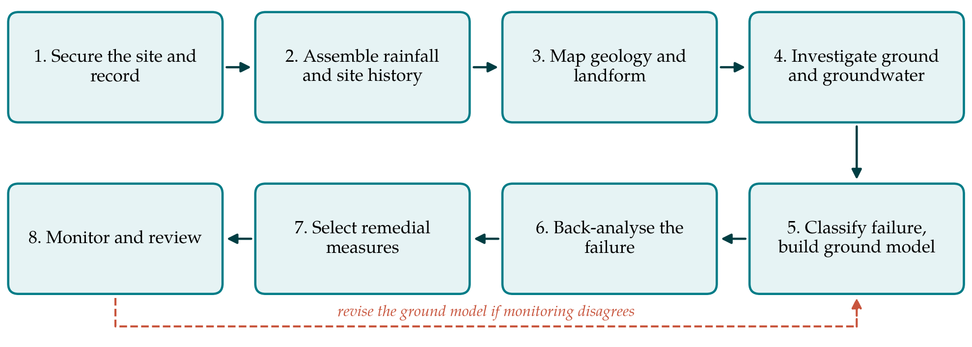
The procedure has eight steps, shown in sequence in Figure 1. The first two can be completed within days of the event. The remainder take weeks to months, depending on access and on how much investigation the consequences of a repeat failure justify.
3.1. Step 1: Secure the site and record it
Clearing debris destroys evidence. Before plant moves in, the scar and deposit should be photographed from fixed points, with a drone if one is available, and the main dimensions measured. The record should capture the shape of the rupture surface, the position of tension cracks behind the crest, seepage points and their relation to geological features, and the state of drains and culverts above and below the cut. Temporary measures, such as diverting surface water away from the crest and sheeting open cracks, reduce the risk of further movement without prejudicing the investigation.
3.2. Step 2: Assemble the rainfall and site history
The rainfall record from the nearest gauges is compiled for the triggering storm and for the preceding weeks, so that both intensity and antecedent wetness can be judged against any regional threshold. Construction records, earlier failures, maintenance history and aerial photographs are gathered at the same time. Old photographs frequently show that a failed cut was sited in a hollow, on an older landslide or below a drainage line, facts that are hard to see once the road is in place.
3.3. Step 3: Map the geology and landform
The scar is a fresh exposure and should be logged as one. Materials are described and graded for weathering, and discontinuities are measured for orientation, spacing, persistence, roughness, aperture and infilling following the suggested methods of the ISRM (1978). The orientations are plotted on a stereonet with the cut face to test for planar, wedge and toppling mechanisms. Mapping is extended to the natural slope above and to adjacent cuts in the same materials, since these show whether the controlling feature is local or runs along the alignment.
3.4. Step 4: Investigate the ground and groundwater
Subsurface work is planned to answer questions left open by the mapping: the depth to rock, the position of the rupture surface beyond the scar, and the groundwater regime. Trial pits and a small number of cored boreholes are usually sufficient for a single cut. Samples are taken from the material in which the rupture surface formed, and shear strength is measured under drained conditions at stresses representative of the shallow depths involved. Piezometers or tensiometers installed at this stage begin a record that later steps depend on.
3.5. Step 5: Classify the failure and build the ground model
The observations are now combined into a ground model: one or more cross-sections showing the materials, structure, pre-failure and post-failure profiles, rupture surface and inferred water conditions, together with a classification of the movement. The model should state the geological control explicitly. Table 1 lists the controls most often met in road cuts, the evidence that points to each and the kind of remedy each calls for. More than one may be present.
| Geological control | Field evidence | Remedial approach |
|---|---|---|
| Joint or bedding dipping out of the face | Planar or stepped rupture surface; stereonet shows daylighting set | Flatten to the dip, or anchor or dowel across the plane |
| Relict joints in weathered rock | Smooth, coated surfaces exposed in apparent soil | Soil nails oriented across the joints; drainage |
| Colluvium over rock | Rupture at the contact; seepage along it | Intercept water at the contact; retain or remove colluvium |
| Permeability contrast within the profile | Seepage line at a consistent level in the scar | Raking drains to the perched level; surface protection |
| Preferential flow paths | Soil pipes, open joints or dykes issuing water | Locate and drain the feature; avoid sealing its outlet |
| Concentrated surface water | Blocked or broken drain above the crest; erosion gullies | Repair and enlarge drainage; line channels |
3.6. Step 6: Back-analyse the failure
Back-analysis asks what combination of strength and pore pressure gives a factor of safety of one on the observed rupture surface. For rotational and compound surfaces, limit equilibrium methods such as those of Bishop (1955) and Morgenstern and Price (1965) are used; for sliding on a discontinuity, the planar and wedge solutions of rock slope engineering apply (Wyllie and Mah, 2004). Strength and water pressure cannot both be found from one equation, so one must be constrained by measurement. The value of the exercise lies in testing the ground model: if failure can only be explained with implausible strengths, the model is wrong (Duncan et al., 2014).
3.7. Step 7: Select the remedial measures
Remedial options fall into four groups: changing the geometry, controlling water, adding structural support and protecting the surface. The ground model determines which will work. Regrading suits soil slopes with room at the crest and is ineffective against a persistent plane dipping at a shallower angle than any practical cut. Drainage addresses the trigger directly and is nearly always part of the solution, with surface channels to keep water off the slope and raking drains to lower pressures within it (Geotechnical Control Office, 1984). Soil nails and rock anchors are designed to cross the identified rupture surface or discontinuity set, following established guidance (Lazarte et al., 2015). Each candidate is checked by re-running the back-analysed model with the measure included and with the design water condition.
3.8. Step 8: Monitor and review
A repair based on a single failure rests on an inferred model, and the observational method offers a disciplined way of dealing with the uncertainty (Peck, 1969). The design records the pore pressures and movements it assumes, instruments are read through at least one wet season, and contingency measures, typically further drains, are defined in advance. If readings depart from the assumptions, the ground model is revised and the design revisited, as the return loop in Figure 1 indicates.
4. Fitting the Procedure to Practice
Road authorities seldom have the means to investigate every failure in depth, and the procedure is meant to be scaled. Steps 1 to 3 and a simplified Step 5 can be done by one experienced person in a few days and cost little; they are sufficient to identify the control in many cases and to prevent the commonest error, which is to rebuild the slope as it was. Steps 4 and 6 are justified where the cut is high, the road has no alternative route, or buildings stand above or below. The outputs of each step should be kept in a slope record, so that the next failure on the same alignment starts from an existing ground model and not from nothing.
The procedure also has a place before failure. The mapping in Step 3, applied to standing cuts in the same geological unit as a failed one, identifies others with the same control, and Table 1 can then be used to rank them for preventive drainage or support.
5. Limitations and What Remains to Be Shown
The procedure is a synthesis of published practice and has not been tested here against real failures. Its usefulness would need to be demonstrated by applying it to a series of cut slope failures and recording whether the control identified at Step 5 was confirmed by later performance, and whether repairs designed through it performed better than conventional reinstatement. Its weakest point is groundwater. Pore pressures at the moment of failure are almost never measured, so back-analysis relies on assumption, and instruments installed afterwards record a slope whose geometry and drainage have changed. Preferential flow is harder still to characterise and is represented in the procedure only through field observation. Finally, the eight steps describe single failures. They do not replace regional hazard assessment or rainfall warning systems, which answer a different question.
6. Conclusion
Rain triggers cut slope failures, and geology decides where and how they occur. The procedure proposed in this article is intended to make that distinction operational: it requires the investigator to record the evidence before it is cleared, to map and classify the failure, to state the geological control in a ground model, to test the model by back-analysis, and to choose and monitor a remedy that addresses the control. It asks for little that is new. Its contribution is to arrange established methods in an order that a road authority can follow and audit, and its practical value remains to be shown by application.
Conflict of interest
To be declared by the author(s) before publication.
Funding
To be declared by the author(s) before publication.