1. Introduction
Soil water content varies over distances of metres, and salinity often varies as sharply. A single probe at a single depth says little about a field, which is why reviews of soil moisture measurement have long pointed to affordable sensor networks as the route to useful spatial coverage (Robinson et al., 2008). Time domain reflectometry remains the reference electromagnetic technique, but its instrumentation is costly. Capacitance probes built on rigid circuit boards brought the price down considerably and are now the workhorses of field networks (Bogena et al., 2007). Printed electronics promises a further step: electrodes deposited by screen or inkjet printing on plastic film, produced by the metre and cut to length (Khan et al., 2015).
The proposition is attractive, and a growing number of printed soil sensors have been described. This communication does not survey them individually. It sets out, from established soil physics and sensor theory, what a printed flexible electrode can measure, where its errors come from, and which questions a reader should put to any report of such a device.
2. What the Electrode Measures
Liquid water has a relative permittivity of about 80 at room temperature, against values of a few units for soil minerals and one for air. The permittivity of the bulk soil therefore rises steeply with volumetric water content, a relation that Topp et al. (1980) established empirically for mineral soils and that underlies every dielectric sensor since. An electrode pair in contact with soil forms a capacitor whose value follows the permittivity of the material within its field.
Salinity enters through conduction. The bulk electrical conductivity of soil depends on the conductivity of the pore water, on how much water there is and how tortuous its paths are, and on conduction along clay surfaces, as formalised by Rhoades et al. (1976). It is the quantity mapped in salinity surveys (Corwin and Lesch, 2005). A sensor that measures both the capacitive and the conductive part of the electrode impedance can in principle estimate water content from one and, using a model such as that of Hilhorst (2000), the pore-water conductivity from the pair. The two parts are not independent in practice. At the low operating frequencies that inexpensive circuits favour, conduction and interfacial polarisation inflate the apparent permittivity, so that a saline soil reads wetter than it is. The frequency, conductivity and temperature sensitivities of low-cost capacitance sensors were characterised by Kizito et al. (2008), and the general theory is reviewed by Robinson et al. (2003).
3. The Printed Interdigitated Electrode
The natural geometry for a printed sensor is the interdigitated electrode: two combs of parallel fingers on one face of the film, with the field fringing out into the material above. Its behaviour is well understood. Mamishev et al. (2004) show that the depth to which the field penetrates scales with the spatial period of the fingers, so that fine fingers sample only a thin layer next to the surface and coarse ones reach further. For soil this is the central design choice. A sensor that probes less than a millimetre responds to the film of water and the few grains touching it, and is hostage to contact. Fringing-field moisture sensors made by ordinary circuit-board processes have been analysed in these terms (Dean et al., 2012), and printing changes the manufacturing route without changing the physics.
Materials follow from the process. Screen printing lays down thick silver or carbon pastes and tolerates coarse features; inkjet printing deposits thin layers of nanoparticle ink that must be sintered at temperatures the substrate can bear (Perelaer et al., 2010). Polyester film is cheap and adequate for low curing temperatures, polyimide withstands more, and paper has been proposed for disposable devices. Silver conducts best but corrodes and migrates in wet saline conditions, while carbon is stable and more resistive. For capacitance sensing the resistance of the fingers matters little. For conductivity sensing it adds in series with the quantity sought.
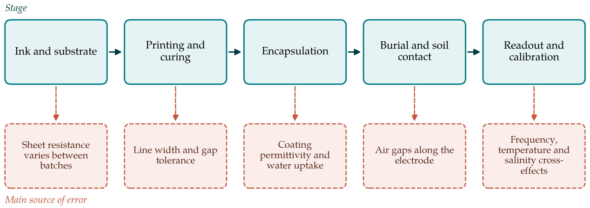
The stages between ink and reading, and the dominant source of error at each, are set out in Figure 1. Table 1 lists the design choices that address them, with the trade each involves.
| Design choice | Benefit | Cost or risk |
|---|---|---|
| Wider finger period | Field reaches further into the soil; less contact-sensitive | Larger sensor; lower capacitance per unit area |
| Higher measurement frequency | Less influence of salinity on the water reading (Kizito et al., 2008) | More demanding circuit and layout |
| Carbon in place of silver ink | Chemically stable in wet saline soil | Higher track resistance |
| Thicker encapsulation | Longer life; better abrasion resistance | Lower sensitivity; slower response |
| Exposed inert contacts for conductivity | Direct measure of bulk conductivity | Polarisation and fouling at the contacts |
| Soil-specific calibration | Removes texture and density effects (Robinson et al., 2008) | Labour for each soil; not transferable |
4. Where the Difficulties Lie
Three difficulties deserve emphasis. The first is encapsulation. Bare printed metal in moist soil will not last, so the electrode must be coated, and the coating places a fixed capacitance in series with the soil. A thick coating protects well and desensitises the sensor; a thin one does the reverse. Polymer coatings also absorb water slowly, which appears as drift over weeks. For conductivity measurement a coated electrode has no galvanic contact with the soil at all and can sense conduction only through its effect on the high-frequency impedance.
The second difficulty is contact. A flexible strip cannot be pushed into undisturbed soil as a rigid tine can. It must be laid in a slot or wrapped on a former, and backfilled soil differs in density and structure from the soil beside it. Any air gap along the face lies exactly where the fringing field is strongest. The third is calibration. Printed dimensions vary from sheet to sheet, so each sensor, or at least each batch, needs its own reference readings in air and water, and the relation between output and water content still depends on texture, bulk density and temperature as it does for every dielectric sensor.
5. Outlook
None of this argues against printed electrodes. Their low cost and freedom of shape suit long strips that average along a crop row, sensors laminated to irrigation tape, and dense arrays in pots and lysimeters, uses for which a rigid probe is awkward. The realistic aim is a sensor good enough to indicate relative wetness and salinity trends at many points, checked against a small number of reference instruments. Reports of printed soil sensors would be more useful if they stated the operating frequency, the coating material and thickness, the finger period, the soils and salinity range used in calibration, and the stability of the reading over months of burial, since those are the facts on which comparison with established probes depends.
6. Conclusion
Printing makes the electrode of a soil sensor inexpensive, and it leaves the measurement problem where it was. Water content can be inferred from the capacitance of a printed interdigitated electrode and salinity from its conductive response, subject to the same cross-sensitivities that affect all low-frequency dielectric sensors and to added uncertainties from encapsulation, soil contact and print tolerance. Attention to those matters, and candid reporting of them, will determine whether printed flexible sensors become dependable field instruments or remain laboratory demonstrations.
Conflict of interest
To be declared by the author(s) before publication.
Funding
To be declared by the author(s) before publication.