1. Introduction
A modern cement plant burns fuel to raise limestone-based raw meal to sintering temperature in a rotary kiln, and it recovers much of the heat internally. Kiln exhaust gas preheats the incoming meal in a tower of cyclones, and air that has cooled the clinker returns to the kiln and calciner as combustion air. Even so, two streams leave the process with useful energy: the gas at the top of the preheater and the excess air vented from the clinker cooler. Energy audits of dry-process kilns consistently identify these streams, together with radiation from the kiln shell, as the main heat losses (Engin and Ari, 2005; Madlool et al., 2011).
Generating electricity from the two gas streams is an established practice, recognised in the European reference document on best available techniques for the sector (Schorcht et al., 2013). Steam cycles are the usual choice for large kilns with hot exhaust. The organic Rankine cycle, or ORC, replaces water with an organic working fluid of lower boiling point and is favoured where the source is cooler or the unit smaller (Tchanche et al., 2011; Quoilin et al., 2013). An early ORC installation on clinker cooler air at a German cement works was described by Legmann (2002).
A plant engineer or consultant asked to judge such a project faces a sequence of decisions, each of which is treated somewhere in the literature but seldom in one place. This article arranges them into a procedure. It is methodological: it proposes what to do and in what order, and it does not report the assessment of an actual kiln.
2. Background
An ORC has the same four processes as a steam Rankine cycle: pumping, evaporation, expansion and condensation. Organic fluids differ from water in ways that suit modest temperatures. Many have a saturated vapour line with positive slope on a temperature-entropy diagram, so the vapour leaves the expander superheated without any need for superheating at the inlet, and droplet erosion of the turbine is avoided. Their low enthalpy drop permits simple, slow-running turbines with few stages. The technology and its history are surveyed by Colonna et al. (2015) and in the handbook edited by Macchi and Astolfi (2017).
Studies of cement plants have compared the options. Khurana et al. (2002) drew up an energy balance for a plant and estimated the cogeneration potential of its waste streams. Wang et al. (2009) compared several power cycles for cement waste heat on the basis of exergy and optimised their parameters. Karellas et al. (2013) analysed a water-steam cycle and an ORC for the same duty and concluded that the steam cycle is the more efficient when the exhaust gas is hot, with the ORC gaining the advantage as the source temperature falls. The procedure below takes these studies as its foundation.
The two sources differ in character. Preheater exit gas is the larger and steadier stream. Its temperature depends chiefly on the number of cyclone stages, since each additional stage transfers more heat to the meal and leaves cooler gas, and it carries fine raw meal dust that is soft but abundant. Cooler vent air is cleaner in composition but carries abrasive clinker dust, and both its flow and its temperature swing with the state of the clinker bed. Some plants extract air from an intermediate point along the cooler to obtain a hotter stream for recovery, at the cost of modifying the cooler. These differences govern the design of the heat exchangers and explain why the two streams are usually treated separately until the choice of layout in Stage 3.
3. The Proposed Procedure
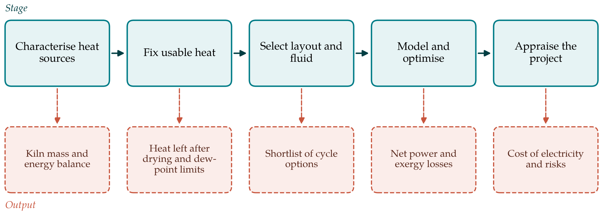
The procedure has five stages, shown in Figure 1 with the output that each passes to the next. The stages are sequential, but a result at a later stage, such as an unacceptable cost, will often send the assessor back to an earlier one.
3.1. Stage 1: Characterise the heat sources
The first task is a mass and energy balance of the kiln system, built from plant measurements: gas flow, temperature, composition and dust loading at the preheater exit and the cooler vent, together with clinker output and fuel input. The method follows the published audits (Engin and Ari, 2005; Khurana et al., 2002). A single design-point balance is not enough. The cooler vent in particular varies in flow and temperature with clinker bed conditions, and kilns start, stop and change feed rate. Records covering at least a full operating campaign should be reduced to duration curves of flow and temperature for each stream.
3.2. Stage 2: Fix the usable heat
Not all the heat in the two streams is free. Preheater gas is commonly ducted through the raw mill to dry the feed, and cooler air may dry coal or alternative fuels. The drying demand, which depends on the moisture of the materials and so on quarry and season, sets a floor on the temperature to which the gas can be cooled by a recovery boiler. A second floor comes from the acid dew point of the gas where sulfur is present, and a third from the downstream filter and fan. The output of this stage is, for each stream, an inlet temperature, a permitted outlet temperature and a flow, each as a range. Pinch analysis offers a disciplined way of confirming that recovery does not displace heat the process needs (Kemp, 2007).
3.3. Stage 3: Select the layout and the working fluid
Two layout questions come first. One is whether the working fluid is evaporated directly in the gas duct or by an intermediate loop of thermal oil or pressurised water. The intermediate loop adds cost and a temperature drop, but it keeps a flammable fluid away from hot, dusty gas, evens out fluctuations and allows the two sources to be combined. The other question is the cycle architecture: whether to include a recuperator, and whether one or two pressure levels are justified. Lecompte et al. (2015) review the architectures proposed for waste heat recovery and the conditions under which each pays.
Fluid selection follows. The thermodynamic criteria are well documented: a critical temperature suited to the source, a dry or isentropic saturation curve, moderate pressures in the evaporator and a condensing pressure not far below atmospheric (Saleh et al., 2007; Chen et al., 2010). Thermal stability at the highest film temperature, flammability, toxicity, global warming potential and availability then narrow the field (Bao and Zhao, 2013). Table 1 summarises the fluid families usually considered for the temperature range of cement waste heat. The stage should end with a shortlist of two or three combinations of layout and fluid.
| Family | Examples | Advantages | Points of caution |
|---|---|---|---|
| Alkanes | n-Pentane, isopentane, cyclopentane | Long industrial record, low cost, low global warming potential | Flammable; explosion protection needed |
| Siloxanes | Linear methyl siloxanes MM and MDM | Suited to higher source temperatures; strongly dry fluids | Deep vacuum in condenser; flammable; large recuperator |
| Aromatics | Toluene | High critical temperature and good thermal stability | Flammable and toxic; sub-atmospheric condensing |
| Hydrofluorocarbons | R245fa | Non-flammable; compact equipment at low source temperature | High global warming potential; subject to phase-down |
| Hydrofluoroolefins | R1233zd(E) | Very low global warming potential; non-flammable | Limited upper temperature; cost |
| Water (reference case) | Steam cycle | Cheap, stable, familiar to plant staff | Needs superheat and hot gas; poor at small scale |
3.4. Stage 4: Model and optimise the cycle
Each shortlisted option is modelled as a steady-state cycle with component efficiencies and minimum temperature differences taken from manufacturers or from the survey literature (Quoilin et al., 2013). Fluid properties should come from a reference-quality library; CoolProp is open and documented (Bell et al., 2014). The evaporating pressure, the degree of superheat and the condensing temperature are then varied to maximise net electrical output, which is the relevant objective when the heat has no other use. Thermal efficiency alone is a misleading target, because a cycle can be efficient while leaving much of the source heat unrecovered.
An exergy balance should accompany the energy balance. It locates the losses, typically in the heat transfer between gas and fluid and in the condenser, and shows whether a change of fluid or pressure level addresses the largest of them (Bejan et al., 1996; Wang et al., 2009). The optimised design is then run across the duration curves of Stage 1 with part-load characteristics for the expander and heat exchangers. The quantity to carry forward is the annual net electricity, after subtracting pump work, the additional fan power needed to overcome the pressure drop of the recovery exchangers, and the cooling system's own consumption.
The condensing temperature deserves particular care. It is set by the cooling medium and the climate and not by the designer, and the output of a cycle working across a modest temperature span is sensitive to it. The model should therefore use the distribution of ambient temperature at the site, in the same way as it uses the duration curves of the heat source, and should not rely on a single design ambient condition.
3.5. Stage 5: Appraise cost and risk
The economic appraisal sets installed cost and operating cost against the value of the electricity, which for most cement plants is purchased power avoided. Module costs and their dependence on size are discussed in the techno-economic survey of Quoilin et al. (2013); budget quotations should replace literature values as soon as they can be obtained. The usual indicators are the levelised cost of the electricity produced and the payback period, each tested for sensitivity to kiln operating hours, electricity price and the drying demand that limits the heat. Where water is scarce, air-cooled condensing should be assumed and its penalty in hot weather included.
Risks that do not appear in the cash flow belong in the same stage. Heat exchangers in dusty gas foul and erode, and the cleaning system and its availability record deserve as much scrutiny as the cycle efficiency. The recovery unit must never constrain the kiln, so bypass ducts and their controls are part of the project. Flammable fluids bring zoning and permitting obligations. Regulation of fluorinated fluids may shorten the useful life of some choices.
4. Fitting the Procedure to a Particular Plant
The weight given to each stage will vary. At a plant with wet raw materials, Stage 2 may show that little preheater heat is left and the project reduces to the cooler air alone, which is cooler and more variable; an ORC is then the natural candidate and the comparison with steam can be brief. At a large kiln with dry feed and a short preheater tower, the exhaust is hotter and the steam reference case in Table 1 must be worked through with the same care as the organic fluids. Plants that already have a long record of process data can complete Stage 1 at a desk. Others will need a measurement campaign, and the uncertainty of gas flow measurement in large dusty ducts should be carried through the later stages and not hidden.
The procedure can also be scaled to the decision at hand. For a first screening, Stages 1 and 2 with a generic conversion efficiency are sufficient to show whether a project deserves study. The full sequence is intended for the feasibility stage that precedes requests for tenders.
5. Limitations and What Remains to Be Shown
The procedure has been assembled from published methods and has not been tested by applying it to a plant. Its usefulness would be shown by a comparison of its predictions with the measured output of an operating unit, in particular the annual energy figure of Stage 4, which depends on part-load models that are less mature than design-point calculations (Lecompte et al., 2015). Steady-state modelling may misjudge a source as unsteady as cooler vent air, and dynamic simulation might be required. The procedure also treats the ORC in isolation. Changes to the kiln line itself, such as an additional preheater stage or a more efficient cooler, reduce the waste heat and may be the better investment, and reviews of energy saving in cement production set waste heat recovery alongside such measures (Madlool et al., 2011). An assessment should state that alternative openly.
6. Conclusion
An organic Rankine cycle on cement kiln waste heat is proven technology whose merit at a given plant depends on local facts: how much heat remains after drying, how steady it is, what electricity costs and what cooling is available. The five-stage procedure proposed in this article orders the questions so that those facts are established before a cycle is designed, and so that the cycle is judged on annual net electricity and cost and not on design-point efficiency. It is offered as a framework for feasibility work, open to correction when tested against operating installations.
Conflict of interest
To be declared by the author(s) before publication.
Funding
To be declared by the author(s) before publication.