1. Introduction
A bracket is a modest component with a demanding job. It carries equipment, pipework or a control surface back to the primary structure, it sees vibration and repeated manoeuvre or road loads throughout its life, and it is produced in numbers too small to justify a forging die. These features explain why brackets were early candidates for laser powder bed fusion (LPBF) in aerospace, motorsport and space hardware. A topology-optimised bracket in a castable aluminium-silicon alloy can be built without tooling, and its organic shape places material only along the load paths (Aboulkhair et al., 2019).
The difficulty lies in fatigue. LPBF aluminium has a very fine cellular microstructure and static strength that matches or exceeds that of the equivalent casting alloy (Aboulkhair et al., 2019). Under cyclic loading the picture is less favourable. Fatigue cracks in these materials start almost without exception at a pore, an oxide film or a surface irregularity, and the scatter in life from one nominally identical specimen to the next is wide (Brandl et al., 2012; Yadollahi and Shamsaei, 2017). A designer who sizes a bracket from handbook tensile data will therefore be optimistic, and one who applies a blanket knock-down factor may give back the mass that the optimisation removed.
This article reviews what the published literature says about the two halves of the problem: how porosity forms in LPBF aluminium, and how it controls fatigue behaviour. It keeps the bracket in view throughout, because thin walls, unmachined surfaces, supports and changing section thickness alter both the defect population and the stress field in ways that standard test bars do not reproduce.
2. Scope and Approach
The review is narrative. It draws on peer-reviewed studies, earlier reviews and published standards known to the field, and it makes no claim to an exhaustive or systematic search. Most of the fatigue evidence concerns AlSi10Mg and the closely related AlSi12, since these near-eutectic alloys solidify over a narrow range and were the first aluminium grades to be processed reliably. High-strength wrought compositions of the 2xxx, 6xxx and 7xxx series tend to crack during solidification under LPBF conditions unless their chemistry or nucleation behaviour is modified (Martin et al., 2017), and they are mentioned only where they change the argument. Studies of pore formation in steels and titanium alloys are cited where the mechanism they reveal is general. No new experimental results are reported here.
3. Why Aluminium Is Prone to Porosity
Aluminium powders present the laser with an unhelpful combination of properties. Reflectivity at the wavelength of the fibre lasers used in most machines is high, thermal conductivity is high, and each particle carries a thin, tenacious oxide skin. A large energy input is needed to form a stable melt pool, yet the pool freezes quickly and wets the previous layer poorly wherever oxide survives (Olakanmi et al., 2015). Low powder density and irregular flow add to the problem by making the spread layer less uniform than that of a denser alloy.
Hydrogen is the second ingredient. Its solubility in liquid aluminium is many times higher than in the solid, so hydrogen taken up by the melt is rejected at the solidification front and nucleates small spherical pores. In LPBF the main source is moisture adsorbed on the powder surface, which the laser dissociates. Weingarten et al. (2015) traced hydrogen porosity in AlSi10Mg to this source and showed that drying the powder, either beforehand or with a low-power laser pass, reduced it. Powder that has been reused or stored in humid air is correspondingly more at risk.
4. Mechanisms of Pore Formation
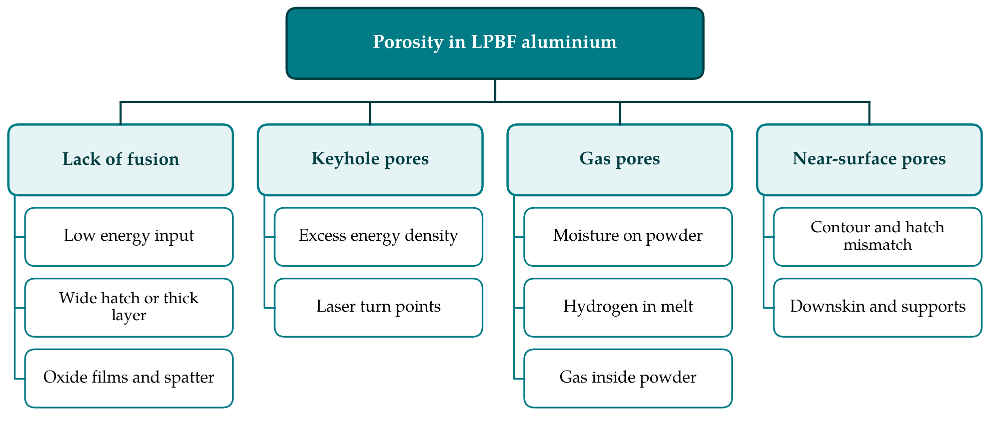
Four families of pore are usually distinguished, and Figure 1 sets them out with their principal causes. The distinction matters because the families differ in size, shape and location, and these three attributes decide how damaging a pore is in fatigue.
4.1. Lack-of-fusion voids
Lack-of-fusion voids appear where neighbouring tracks or successive layers fail to overlap. They are irregular, flattened in the plane of the layer, often several particle diameters across, and may contain unmelted powder. Tang et al. (2017) showed that their occurrence can be predicted from geometry alone: when the melt pool is too narrow for the hatch spacing or too shallow for the layer thickness, unfused pockets remain. In aluminium the effect is aggravated by oxide. Films swept aside by the melt, or formed on spatter particles that land on the bed, prevent wetting between tracks and leave crack-like gaps, a link established for AlSi10Mg by Tang and Pistorius (2017).
4.2. Keyhole pores
Raising the energy density to cure lack of fusion carries its own risk. Above a threshold the metal surface boils, recoil pressure drives a deep vapour cavity into the pool, and the melting mode changes from conduction to keyhole. The transition was documented for LPBF by King et al. (2014) in stainless steel, and high-speed synchrotron imaging later showed the keyhole fluctuating and pinching off bubbles at its base (Cunningham et al., 2019). Simulation attributes the instability to the interplay of recoil pressure and surface-tension-driven flow (Khairallah et al., 2016). Keyhole pores are rounded and lie deep in the track. They are especially likely where the laser decelerates and reverses at the end of a scan vector, because the local energy input rises there.
4.3. Gas and near-surface pores
Hydrogen pores are the smallest of the four families and are close to spherical. Aboulkhair et al. (2014) found that the pore type in AlSi10Mg shifted from small metallurgical pores to larger irregular ones as scan speed increased, and that a scan strategy which remelts each layer could bring relative density close to full. Gas trapped inside atomised powder particles adds a minor contribution of the same kind.
The fourth family is defined by position. Many machines trace the outline of each slice with a contour scan and fill the interior with hatch vectors. If the two do not overlap adequately, or if the hatch vectors end just inside the contour where turn-point keyholing occurs, a band of pores forms a fraction of a millimetre below the surface. Overhanging, downward-facing surfaces and regions near supports are prone to a similar concentration, since heat is conducted away poorly through loose powder. X-ray computed tomography of AlSi10Mg has confirmed that pores are not uniformly distributed through a part (Maskery et al., 2016).
5. From Pores to Fatigue Cracks
The static tensile properties of LPBF aluminium are tolerant of a modest pore fraction. Fatigue is not, and the reason is that fatigue strength depends on the worst defect in the stressed volume and hardly at all on the average density. Murakami (2002) expressed this for metals in general: a small defect behaves like a short crack whose severity is measured by the square root of its area projected on the plane normal to the maximum principal stress, and the fatigue limit falls slowly but steadily as that parameter grows. The Kitagawa-Takahashi diagram, which joins the plain fatigue limit to the long-crack threshold, gives the same idea in graphical form (Kitagawa and Takahashi, 1976).
Applied to additively manufactured alloys, this framework accounts for much of what is observed. Beretta and Romano (2017) compared the defect sensitivity of additive and conventionally produced materials and concluded that both obey the same short-crack description once defect size is taken into account. Romano et al. (2018) went further for AlSi10Mg, combining computed tomography with the statistics of extremes to estimate the largest defect expected in a given volume and predicting fatigue strength from it. Fractography in independent studies agrees: initiation sites are pores or oxide defects at or just below the surface, and longer lives go with smaller initiating defects (Tang and Pistorius, 2017; Siddique et al., 2015).
Three attributes of a pore therefore count. Size comes first. Shape is second, since a flat lack-of-fusion void lying across the load acts as a sharper notch than a sphere of equal projected area, which is one reason specimens loaded along the build direction often perform worse than those loaded in the layer plane. Position is third: a pore that breaks the surface or lies within about its own diameter of it is markedly more harmful than the same pore in the interior (Sanaei and Fatemi, 2021; du Plessis et al., 2020). Table 1 summarises how each pore family rates on these attributes and what can be done about it.
| Pore family | Typical form and location | Relevance to fatigue | Usual countermeasure |
|---|---|---|---|
| Lack of fusion | Flat, irregular, between tracks or layers | Most severe, above all when normal to the load | Adequate energy input, closer hatch, thinner layer |
| Oxide-related void | Crack-like film with unfused gap | Severe; hard to close by pressure | Low-oxygen atmosphere, spatter removal by gas flow |
| Keyhole pore | Rounded, deep in track, at vector ends | Moderate; severe if near the surface | Lower energy density, turn-point power control |
| Hydrogen pore | Small, spherical, dispersed | Minor unless clustered or at the surface | Powder drying, humidity control, platform heating |
| Near-surface band | Row of pores below the contour | Severe once exposed by machining or left under a rough skin | Contour and hatch overlap, adjusted downskin parameters |
Surface condition interacts with porosity. The as-built skin of an LPBF part carries partly fused particles and layer steps that act as notches in their own right, and several studies report that as-built fatigue strength falls well below that of machined material (Mower and Long, 2016). Machining removes the skin, but it can also expose the near-surface pore band, so the benefit is not guaranteed. Aboulkhair et al. (2016) found that heat treatment improved the fatigue behaviour of AlSi10Mg more than machining did, which indicates that microstructure and residual stress also contribute and that porosity is not the whole story.
6. What Changes in a Bracket
Nearly all of the evidence above comes from cylindrical or flat coupons, most of them machined. A bracket differs in at least four respects. Its walls and struts are thin, so the contour region and its pore band occupy a large share of the cross-section. Most of its surface cannot be reached by a cutting tool and stays as built, including downward-facing surfaces and the scars left by support removal. Its section thickness changes along the build height, which alters local cooling and may move a parameter set tuned on bulk cubes towards either lack of fusion or keyholing. And its fatigue-critical locations are fillets and lug bores, where stress gradients are steep and the highly stressed volume is small.
These differences pull in opposite directions. A small stressed volume lowers the chance of containing a large defect, which is the favourable side of the statistical size effect. The concentration of pores and roughness at exactly the surfaces where bending stress peaks works the other way. The defect-based approach can in principle handle both, provided the defect population is characterised on material that is representative of the part and not only on witness bars. Density measured by the Archimedes method is a poor substitute for this purpose, since it reports an average and is insensitive to the few large pores that matter (Spierings et al., 2011).
Qualification documents reflect this reasoning. The alloy specification for powder bed fused AlSi10Mg sets requirements on feedstock, processing and finished-part properties (ASTM International, 2018), and the standard issued by NASA for spaceflight hardware asks for a qualified process, witness specimens built with every part and a classification of parts by the consequence of failure (NASA, 2017). Neither removes the need for the designer to judge how far coupon data apply to a given bracket geometry.
7. Mitigation Routes
Process control is the first line of defence. A parameter window that avoids both lack of fusion and keyholing, dry powder with a controlled reuse history, a shielding gas flow that carries spatter away from the bed, and attention to contour settings together remove most of the large defects. Platform heating reduces thermal gradients and has been associated with lower scatter in fatigue results (Brandl et al., 2012; Siddique et al., 2015).
Hot isostatic pressing closes internal pores that are not connected to the surface. For AlSi10Mg its value is debated in the review literature. The temperatures involved coarsen the silicon network and reduce static strength, gas pores may reopen during later solution treatment, and oxide-lined voids do not bond even when pressed shut (Sanaei and Fatemi, 2021). Surface treatments such as machining of accessible faces, shot peening and chemical or abrasive polishing address the skin, with peening adding compressive residual stress. For a bracket the practical question is which of these can reach the critical fillets.
8. Gaps and Directions for Further Work
Several questions remain open. The transfer of defect statistics from coupons to components is the most pressing: published defect-based predictions are convincing for test bars, and far fewer studies follow the method through to a geometrically complex part tested under realistic loading. Variable amplitude and multiaxial loading, which is what brackets actually see, are thinly covered compared with constant-amplitude axial tests. The combined effect of rough as-built surfaces and sub-surface pores needs a description that treats them as one interacting defect and not as two separate knock-down factors.
On the process side, in-situ monitoring of the melt pool promises to locate defects as they form, but the link between a monitoring signal and a fatigue-relevant pore is not yet firm enough to replace tomography. The probability of detecting a pore of a given size by computed tomography in a real part, which depends on wall thickness and voxel size, also deserves systematic treatment. Finally, the newer high-strength alloys designed for LPBF change the microstructure in which pores sit, and it should not be assumed that defect sensitivity measured on AlSi10Mg carries over unchanged.
9. Conclusion
The literature gives a coherent account of why LPBF aluminium parts fail in fatigue where they do. Pores arise from identifiable causes: insufficient overlap, unstable keyholes, hydrogen from damp powder, and poorly matched contour and hatch scans. Fatigue life is set by the largest of them near the surface of the highly stressed region, and short-crack models built on defect size describe coupon behaviour well. For brackets, thin sections and unmachined surfaces make the near-surface defect population the central concern. Designers are best served by characterising that population on representative geometry and by treating mean density as a process check only, never as a measure of fatigue quality.
Conflict of interest
To be declared by the author(s) before publication.
Funding
To be declared by the author(s) before publication.