1. Introduction
Induced drag falls as span grows, and the pursuit of efficiency has pushed transport, solar-powered and surveillance aircraft towards wings of very high aspect ratio. Built in carbon fibre composite to save weight, such wings are flexible enough that tip deflections amounting to a substantial fraction of the semispan occur in normal flight. The classical flutter calculation, which treats small vibrations of the undeformed wing, then describes a structure that does not exist in the air. Patil et al. (2001) showed for a high-altitude long-endurance configuration that the flutter speed computed about the curved, loaded shape can be far lower than the linear estimate, mainly because bending deflection couples the edgewise and torsional motions. Experiments on a slender model wing confirmed the sensitivity of the flutter boundary and of the limit-cycle response that follows it to geometric nonlinearity (Tang and Dowell, 2001).
The loss of the Helios prototype in turbulence, after the aircraft took up a high-dihedral shape and entered a divergent pitch oscillation, led its investigators to recommend analysis methods that treat large deformation, flight dynamics and aeroelasticity together (Noll et al., 2004). A broad literature on nonlinear aeroelasticity of slender wings has since grown up and is reviewed by Afonso et al. (2017).
High-fidelity coupled simulation is available but expensive, and flutter clearance is an exercise in repetition across mass cases, speeds, altitudes and failure states. Reduced order models, which keep the dominant dynamics in a few tens of states, are the practical answer (Dowell and Hall, 2001; Lucia et al., 2004). This article sets out a procedure for constructing one for a high aspect ratio composite wing. It reports no computed results. Its purpose is to put the steps, the choices within each and the checks that should accompany them in one place.
2. Background
Three bodies of established work underlie the procedure: the reduction of a composite wing to a beam, the representation of unsteady aerodynamics in a few states, and the solution of the flutter equations.
2.1. Composite beams and tailoring
A slender wing behaves structurally as a beam, but a laminated box is not a simple one. Off-axis plies couple bending to twist, and that coupling is the mechanism of aeroelastic tailoring, by which a designer steers divergence and flutter speeds through the layup (Shirk et al., 1986). The modern treatment separates the problem into a two-dimensional cross-sectional analysis, which yields a fully populated stiffness matrix for the section, and a one-dimensional geometrically exact beam analysis that is valid for arbitrarily large displacement and rotation provided strains stay small (Hodges, 2006). This split is itself a model reduction, and an accurate one for wings whose chord is small beside their span.
2.2. Unsteady aerodynamics in reduced form
Flutter analysis needs the aerodynamic forces produced by wing motion, including the lag caused by the shed wake. For a thin section in incompressible flow Theodorsen (1935) gave these in the frequency domain. Lifting surface methods, of which the doublet-lattice method is the workhorse, extend the idea to finite wings in subsonic flow (Albano and Rodden, 1969). Both deliver forces as tabulated functions of reduced frequency. To place them in a time-domain or state-space model they are fitted with rational functions, at the cost of added lag states, and the minimum-state formulation keeps that cost small (Karpel, 1982). Finite-state inflow theory reaches the same end directly from the governing equations (Peters et al., 1995). The unsteady vortex-lattice method works in the time domain, follows a deforming wake and can itself be linearised and reduced (Murua et al., 2012). Where shocks matter, reduced models are identified from computational fluid dynamics by proper orthogonal decomposition or by Volterra and related system identification methods (Hall et al., 2000; Silva, 2005).
2.3. Flutter solution
With structure and aerodynamics in compatible form, flutter is found as the speed at which a root of the coupled system crosses into the unstable half-plane. Frequency-domain aerodynamics lead to iterative schemes such as the p-k method, in which frequency and damping are found by repeated solution at matched reduced frequency. State-space aerodynamics give an ordinary eigenvalue problem. Both routes are described in the standard text of Hodges and Pierce (2011).
3. The Proposed Procedure
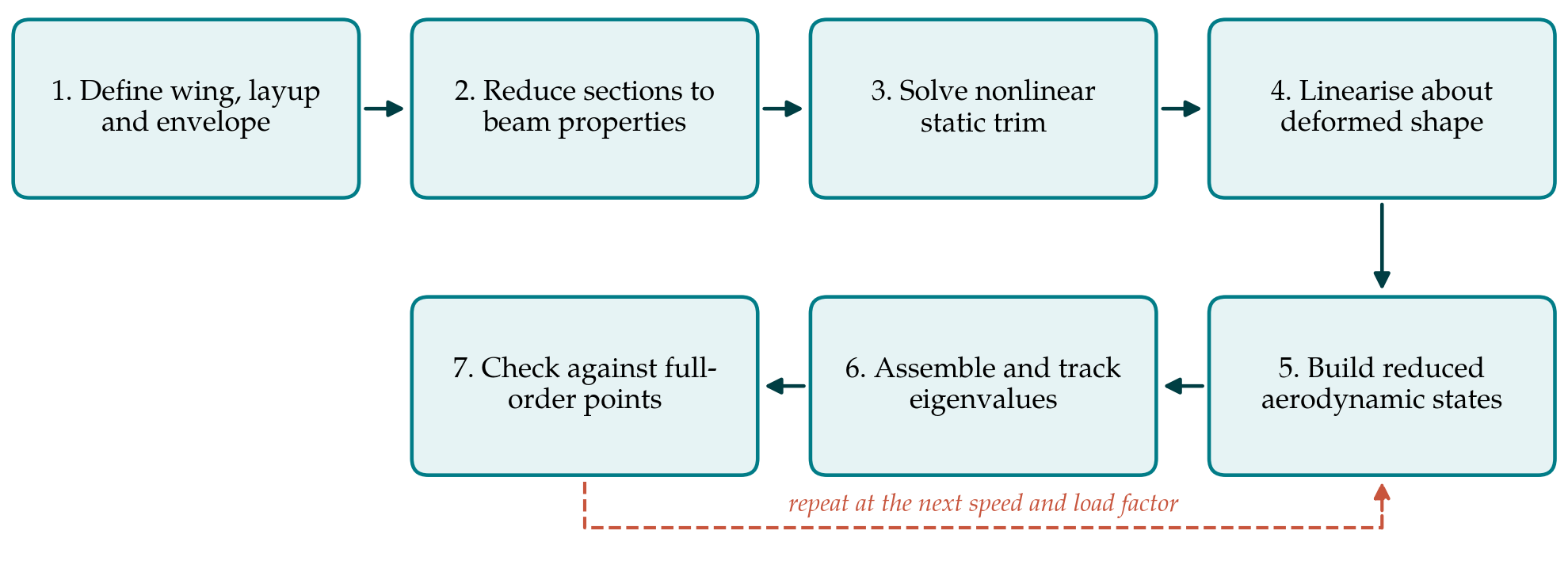
The procedure has seven steps, shown in sequence in Figure 1. The first two are performed once for a given design. Steps three to six are repeated at each flight condition, because the equilibrium shape, and with it the linearised model, changes with speed and load factor. The seventh is a periodic check.
3.1. Step 1: Define the wing, the layup and the envelope
The analyst records the planform, the spanwise distribution of section geometry and laminate, the non-structural masses including fuel states, and the range of speed, altitude and load factor to be cleared. The boundary condition at the root is fixed at this point: a cantilever is adequate for component studies, while a very flexible aircraft may need the rigid-body degrees of freedom retained, since its lowest elastic frequencies can approach those of the flight dynamic modes (Patil et al., 2001).
3.2. Step 2: Reduce the sections to beam properties
A cross-sectional analysis is run at a set of spanwise stations to obtain, for each, the six-by-six stiffness matrix, the mass per unit length, the mass moments of inertia and the positions of the shear centre and centre of mass. The off-diagonal stiffness terms must be kept. Discarding them reduces the wing to an isotropic equivalent and removes exactly the tailoring effect a composite design relies on. The output of this step is a table of sectional properties against span.
3.3. Step 3: Solve the nonlinear static aeroelastic trim
For each speed, altitude and load factor, the geometrically exact beam is loaded with steady aerodynamic forces and gravity, and the equilibrium is found iteratively, updating the aerodynamic loads as the wing deforms. A nonlinear lifting-line or steady vortex-lattice model on the deformed geometry is sufficient in attached subsonic flow. The result is the deflected shape with its internal forces. Both are needed, since prestress alters stiffness as well as geometry.
3.4. Step 4: Linearise about the deformed shape and choose a basis
Tangent stiffness and mass matrices are formed at the equilibrium and the natural modes computed. On a strongly bent wing these modes differ from the jig-shape modes: torsion and edgewise bending, which are independent on a straight wing, combine. A small number of modes, enough to span the frequency range of interest with margin, forms the structural basis. When stores or control surfaces are attached, component mode synthesis offers a consistent way of assembling the basis from substructures. The basis must be recomputed, or at least checked, at each trim state and not carried over from the undeformed wing.
3.5. Step 5: Build the reduced aerodynamic model
The aerodynamic reduction is chosen to suit the regime, and Table 1 compares the main options. For low-speed, very high aspect ratio wings, strip theory with finite-state inflow is cheap, already in state-space form and easily evaluated on a curved wing. Where three-dimensional effects or wake geometry matter, a linearised unsteady vortex-lattice model about the deformed shape, reduced by balanced truncation or modal projection, is the natural choice. Doublet-lattice forces with a rational fit remain convenient when an industrial linear toolchain already exists, though the lattice must then follow the deformed surface. In transonic flow a model identified from a nonlinear flow solver is required.
| Approach | Form | Suits | Main limits |
|---|---|---|---|
| Strip theory with finite-state inflow (Peters et al., 1995) | State space | Low speed, very slender wings | No spanwise interaction or tip effects |
| Linearised unsteady vortex lattice (Murua et al., 2012) | State space, large then reduced | Deformed wings, wake and interference effects | Incompressible, attached flow only |
| Doublet lattice with rational fit (Karpel, 1982) | Frequency domain fitted to lag states | Subsonic compressible flow, existing toolchains | Fit quality; panels fixed to a reference shape |
| Proper orthogonal decomposition (Hall et al., 2000) | Projected flow-solver modes | Transonic flow about a fixed mean state | Snapshot dependent; costly to rebuild |
| Volterra or impulse identification (Silva, 2005) | Identified input-output model | Transonic flow with mild nonlinearity | Training signals; validity near training state |
3.6. Step 6: Assemble the coupled system and track its roots
Structural and aerodynamic states are combined into one first-order system at each flight condition, and its eigenvalues computed. Damping and frequency are followed from condition to condition, with roots matched by eigenvector correlation and not by sorting on frequency, since modes cross and exchange character as the wing bends. Flutter onset is the lowest speed at which a root reaches zero damping along a path of physically consistent trim states. The path matters. Increasing speed at constant load factor and increasing load factor at constant speed approach the boundary through different shapes.
3.7. Step 7: Check against full-order solutions
A reduced model earns trust by comparison. At a few conditions spread across the envelope, including the most deformed, the trim shape, the modal frequencies and the damping trend should be compared with a higher-order solution, for example a shell finite element model coupled to the unreduced aerodynamic method. Disagreement points to the step at fault: a trim error to the beam properties or the steady loads, a frequency error to the basis, a damping error to the aerodynamic reduction.
4. Using the Procedure in Design
Three practical points follow from the structure of the method. Because the beam properties of the second step are an explicit function of the layup, the procedure fits inside a tailoring loop in which ply angles and thicknesses are design variables; only the cross-sectional analysis and the steps after it need to be rerun. Because each flight condition is independent once the properties are known, the loop over the envelope parallelises trivially. And because the model is small, it supports studies that are out of reach at full order, including propagation of uncertainty in ply properties and mass distribution to the flutter speed, a subject on which Pettit (2004) set out the main needs.
The linearised model predicts onset only. Beyond the boundary a slender wing typically settles into a limit-cycle oscillation whose amplitude depends on structural and aerodynamic nonlinearity, including stall (Patil and Hodges, 2004). Where that amplitude is of interest, the same beam and reduced aerodynamic states can be marched in time with the nonlinear terms retained.
5. Limitations and What Remains to Be Shown
The procedure is proposed and has not been validated in this article. Its elements are individually well established, but their combination for a particular wing would need to be demonstrated in at least three respects. The beam idealisation should be tested against a shell model of the same wing box near the root and at ply drops, where section warping is restrained and the slender-beam assumption is weakest. The aerodynamic reduction should be tested for the reduced-frequency range and the deformation levels actually encountered, since a rational fit or a truncated basis that is adequate for a straight wing is not guaranteed to remain so for a curved one. And the predicted boundary should be compared with wind tunnel data on a flexible model of the kind used by Tang and Dowell (2001).
Some physics lies outside the scope altogether. Attached-flow aerodynamics will not predict stall flutter. Small-strain beam theory excludes local buckling of thin skins, which can change effective stiffness before the global instability is reached. Free-play in control surfaces and store attachments introduces its own nonlinearity. An analyst using the procedure should state which of these have been considered and how.
6. Conclusion
For a high aspect ratio composite wing the flutter question has to be asked about the wing as it flies, bent and prestressed, and asked many times over. The procedure proposed here answers it with a chain of reductions, each of which keeps the feature that matters: the sectional analysis keeps bend-twist coupling, the exact beam keeps large deflection, the modal basis about the trim shape keeps the changed mode character, and the aerodynamic state-space model keeps the wake lag. The price is a set of assumptions that must be checked for each application, and that checking remains to be done.
Conflict of interest
To be declared by the author(s) before publication.
Funding
To be declared by the author(s) before publication.