1. Introduction
Friction in the engine, transmission, tyres and brakes consumes a large share of the fuel energy of a conventional passenger car (Holmberg et al., 2012). An electric powertrain removes most of the engine-related losses, and the total frictional loss of a battery electric car is considerably smaller than that of a combustion-engine car (Holmberg and Erdemir, 2019). What remains matters more. With a fixed battery capacity, any loss in the driveline translates directly into range, and the reduction gearbox between motor and wheels becomes one of the few places where a lubricant can still make a measurable difference.
The simplest lever is viscosity. Thinner oil is easier to shear and to move, so the drag of gears and bearings falls. The same change thins the film that keeps loaded surfaces apart. Transmission engineers have managed this trade-off for decades, but the electric drive unit shifts its terms: motor speeds are much higher than engine speeds, torque is available from standstill, and the fluid is often asked to cool the motor as well as lubricate the gears (Farfan-Cabrera, 2019; Chen et al., 2020). This article reviews what the published literature establishes about low-viscosity lubricant behaviour under those conditions.
2. Approach
The review is narrative. It combines recent survey papers on electric vehicle tribology with the older and more fundamental literature on gear power loss, elastohydrodynamic lubrication (EHL) and gear surface failure, on which any assessment of thin oils must rest. No systematic search was performed and the selection reflects the sources most widely relied on in the field. Because little component-level test data from production drive units is openly published, the discussion is framed in terms of mechanisms and established trends, and specific loss or life figures are not quoted.
3. The Operating Environment of an Electric Drive Unit
A typical electric drive unit couples a traction motor to the differential through a single-speed reduction, usually in two helical stages. The motor may run at speeds several times those of a combustion engine, so the input pinion and its bearings experience very high pitch-line and rolling velocities, while the output stage sees lower speed and high torque. Peak torque is delivered at or near zero speed, where no hydrodynamic film has formed, and regenerative braking loads the reverse flanks of the teeth. The duty therefore spans a wider range of lubrication regimes than a conventional gearbox, with the two extremes often present in the same housing at the same time (Farfan-Cabrera, 2019).
Integration adds further demands. In many designs one fluid lubricates the gears and bearings and is also sprayed or circulated over the stator end-windings and rotor to remove heat. The fluid then meets copper conductors, insulation varnish, polymers and electrical potential differences, and its thermal conductivity, heat capacity, electrical resistivity and compatibility with copper become design properties alongside the familiar tribological ones (Chen et al., 2020; Tung et al., 2020). Stray currents can also pass through bearings and gear contacts, producing electrical damage that depends partly on the lubricant (He et al., 2020). Lower viscosity helps heat transfer and pumping, which is a second reason, beyond efficiency, for the move to thinner fluids.
4. Power Loss and the Case for Low Viscosity
Gearbox power loss is conventionally divided into load-dependent and load-independent parts, each arising in gears, bearings and seals (Höhn et al., 2009; Michaelis et al., 2011). Load-dependent losses come from sliding and rolling friction in the loaded contacts. Load-independent, or spin, losses are present whenever the shafts turn: oil is churned, squeezed out of the meshing tooth spaces and dragged through bearings, and air and oil mist are pumped by the rotating gear bodies.
4.1. Load-independent losses
Spin losses grow steeply with speed and are the natural target for viscosity reduction in a high-speed gearbox. For dip-lubricated gears, Changenet and Velex (2007) developed churning loss correlations from experiments in which immersion depth, speed, geometry and fluid properties were varied, and Seetharaman and Kahraman (2009) formulated a physical model that separates drag on the gear faces and periphery from the pocketing loss in the mesh. Both show the influence of viscosity to depend on the flow regime: it is strongest at low and moderate speed and weakens when inertia forces dominate, at which point oil density, immersion depth and housing geometry matter more.
Windage, the loss associated with air and oil mist around the gear, rises with a high power of speed and was first characterised for large high-speed gears by Dawson (1984), with later experimental and theoretical work by Diab et al. (2004). It is almost independent of oil viscosity. Computational fluid dynamics is now used to predict oil distribution and spin losses for specific housings (Concli and Gorla, 2016; Liu et al., 2017). The practical reading of this literature is that thinner oil gives a real reduction in spin loss, but that at the very highest speeds the returns diminish and the oil quantity, its delivery by jet or baffle, and aeration become as important as viscosity.
Rolling bearings deserve separate mention. Those on the motor-side shaft run at the highest speeds in the unit and contribute a substantial part of the load-independent loss, through rolling resistance and the drag of oil displaced by the rolling elements (Michaelis et al., 2011). Lower viscosity reduces this drag directly. At the same time, lightly loaded rolling elements at very high speed may slide instead of roll, and a thin film offers less protection against the smearing that results. Bearing selection, cage design and the quantity of oil admitted to the bearing therefore interact with viscosity, and reducing oil flow to a bearing to save drag has to be weighed against its cooling.
4.2. Load-dependent losses
In the loaded mesh the picture is less favourable to thin oil. When the surfaces are fully separated, friction arises from shearing the pressurised film, and it is governed less by the low-pressure viscosity than by the high-pressure rheology of the base fluid. Molecular structure determines this EHL friction: fluids built from flexible, linear molecules give lower traction than those with bulky or rigid structures (Spikes and Jie, 2014). A reduction in viscosity that moves the contact from full-film into mixed lubrication can raise the friction coefficient, because asperity contact carries part of the load. Michaelis et al. (2011) make the point that the best lubricant for efficiency is therefore not simply the thinnest, and that the balance depends on the share of operating time spent at high load.
5. Film Thickness and Surface Durability
The separation of gear teeth and rolling elements is described by EHL theory, in which elastic flattening of the surfaces and the rise of viscosity with pressure combine to produce a thin, nearly parallel film (Dowson and Higginson, 1966). The regression formulae of Hamrock and Dowson (1977) and their line-contact counterparts show film thickness increasing with the product of entrainment speed and inlet viscosity raised to a power of roughly two-thirds, and with the pressure-viscosity coefficient, while depending only weakly on load. The ratio of film thickness to composite surface roughness, the specific film thickness or lambda ratio, has long been used to indicate the lubrication regime and the likelihood of surface distress (Tallian, 1967).
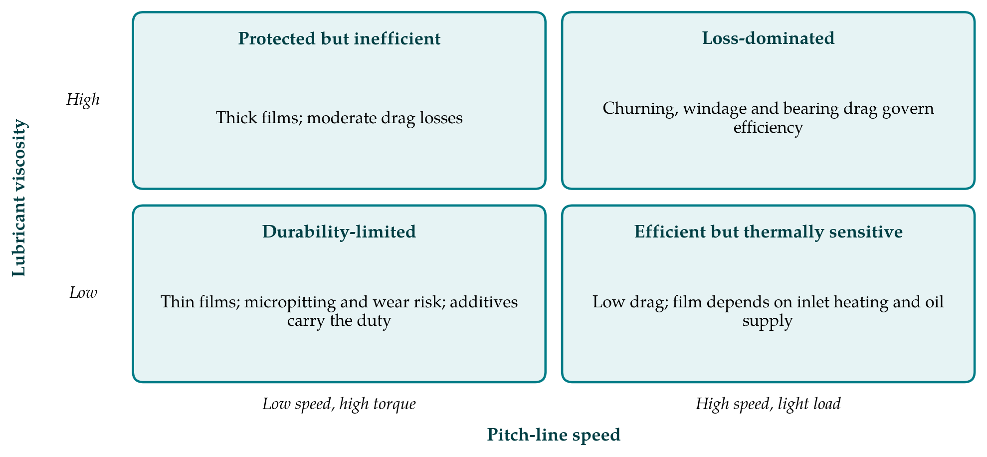
On this basis high speed appears to compensate for low viscosity, and at the motor-side pinion it partly does. Two effects limit the benefit. The viscosity that counts is that at the temperature of the surfaces entering the contact, and both bulk and flash temperatures rise with speed and sliding, so the effective viscosity falls just where the nominal calculation predicts the thickest film. Shear heating in the inlet and the difficulty of keeping the inlet supplied with oil at very high speed reduce the film further. At the output stage, speed is low and torque is high, and a thin fluid gives a film that may be smaller than the surface roughness. Figure 1 sets out the four combinations of speed and viscosity in simplified form.
5.1. Micropitting, pitting and wear
Micropitting is a form of surface-initiated rolling contact fatigue at the scale of the roughness. It appears as a matt grey band on the tooth flank, alters the profile and can progress to macropitting. It is associated with low specific film thickness and with sliding, and the calculation method of ISO/TS 6336-22 assesses the risk by comparing the minimum specific film thickness in the mesh with a permissible value obtained from a test on the lubricant (ISO, 2018). Olver (2005) reviewed the mechanisms of rolling contact fatigue and the role of roughness-induced stress, and Morales-Espejel and Brizmer (2011) modelled micropitting as a competition between surface fatigue and mild wear in rolling-sliding contacts. Lowering viscosity moves a gear set towards the conditions in which these mechanisms operate, unless surface finish is improved in step.
5.2. Scuffing
Scuffing is sudden adhesive damage that occurs when the lubricant film and any boundary film fail together. The classical criterion is that of Blok (1937), who proposed that scuffing occurs when the contact temperature, the sum of the bulk temperature and the momentary flash temperature, reaches a critical value for the combination of lubricant and materials. Flash temperature rises with sliding speed, so high pitch-line velocities are inherently more demanding, and Höhn and Michaelis (2004) showed that oil temperature influences scuffing, micropitting, pitting and wear in different ways. Scuffing capacity is rated with the FZG procedure of ISO 14635-1 (ISO, 2000), which runs at a fixed, moderate speed and was not conceived for the speeds of electric drive units.
6. Fluid and Additive Responses
If the hydrodynamic film is thinner, more of the protection must come from elsewhere. Table 1 summarises the requirements placed on a low-viscosity drive unit fluid and the tension each has with the others.
| Requirement | Why it arises | Tension with other requirements |
|---|---|---|
| Low spin losses | High shaft speeds make churning and bearing drag a large share of loss | Favours low viscosity, which thins the protective film |
| Low traction in loaded contacts | Mesh friction depends on high-pressure rheology of the base oil | Base oil choice also sets seal compatibility and cost |
| Micropitting and wear protection | Low specific film thickness at the low-speed, high-torque stage | Anti-wear chemistry may attack copper or raise conductivity |
| Scuffing resistance | High sliding speeds raise flash temperature | Active sulfur additives are restricted by copper compatibility |
| Motor cooling | Shared fluid removes heat from windings and rotor | Low viscosity helps; aeration at high speed impairs heat transfer |
| Electrical and material compatibility | Contact with windings, insulation, sensors and stray currents | Limits ionic additives relied on for surface protection |
6.1. Base oil selection
The choice of base oil sets the starting point. Synthetic hydrocarbons and certain esters combine a low-temperature viscosity that keeps drag down with a relatively high viscosity index, so less film is lost as the fluid warms, and their molecular flexibility gives low EHL traction (Spikes and Jie, 2014). Low viscosity brings its own practical limits, among them volatility, and the fluid must retain its viscosity under prolonged shearing in the mesh, which restricts reliance on polymeric viscosity modifiers.
6.2. Additive chemistry
Additives take over where the film is insufficient. Friction modifiers, including organic amphiphiles and molybdenum compounds, lower friction in mixed and boundary lubrication by forming low-shear-strength surface layers (Spikes, 2015). Anti-wear and extreme-pressure additives based on phosphorus and sulfur form sacrificial films that prevent adhesion. In a drive unit that shares its fluid with the motor these chemistries are constrained: sulfur species that are effective against scuffing can corrode copper, and ionic or polar additives influence the electrical properties of the fluid (Chen et al., 2020; Tung et al., 2020). The published surveys describe a formulating problem with more simultaneous constraints than a conventional gear oil faces.
7. Test Methods and Gaps in the Evidence
The standard instruments for rating gear lubricants, the FZG scuffing, micropitting and efficiency tests, operate at pitch-line speeds well below those at the input stage of an electric drive unit. Their rankings cannot be assumed to carry over, because the balance between flash temperature, film formation and additive reaction rate changes with speed. High-speed variants of these rigs and component tests on complete drive units exist in industry, but few results are openly published, and the review papers cited here repeatedly note the shortage (Farfan-Cabrera, 2019; Tung et al., 2020).
Several specific gaps follow. Film thickness and traction data for very low viscosity fluids at high entrainment speeds, where thermal and starvation effects dominate, are sparse. The micropitting behaviour of such fluids on gears with improved surface finish has not been mapped publicly in a way that would allow the benefit of superfinishing to be traded against viscosity. The effect of entrained air on both lubrication and cooling at high speed is poorly quantified. And the interaction between electrical stress and tribological film formation, relevant to bearings in particular (He et al., 2020), is at an early stage of study. Each of these would benefit from test methods agreed across the industry.
8. Conclusion
The literature gives a consistent account of what lowering lubricant viscosity does in a high-speed reduction gearbox. Load-independent losses fall, most clearly at low and moderate speed and less so where inertia and windage take over. Loaded contacts respond in a more complicated way, since their friction depends on base oil structure and on whether asperities touch. Film thickness declines, with thermal effects eroding much of the help that speed would otherwise give, and the risk of micropitting at the high-torque stage and of scuffing at the high-speed stage rises. The burden moves to surface finish, base oil selection and additive chemistry, and the last of these is restricted by the fluid's contact with the motor. Thin fluids are plainly workable, as their growing use shows, but the published evidence base at representative speeds remains narrow, and openly reported high-speed test methods are the most pressing need.
Conflict of interest
To be declared by the author(s) before publication.
Funding
To be declared by the author(s) before publication.