1. Introduction
A fixed prosthesis supported by several implants is rigid, and the implants beneath it have none of the physiological mobility of teeth. Errors in the recorded implant positions are therefore transferred to the framework as misfit. How much misfit is tolerable has never been defined with confidence, and the aim in practice is to keep it as small as the method allows (Sahin and Cehreli, 2001). The conventional method, a splinted open-tray impression poured in stone, has known sources of error but a long record of use.
Intraoral scanners record implant positions optically by capturing scan bodies attached to the implants (van der Meer et al., 2012). For single implants and short spans their accuracy is generally accepted. For the complete edentulous arch the picture is mixed. An early clinical pilot study concluded that the scanner tested was not accurate enough for multiple implants in the edentulous mandible (Andriessen et al., 2014), while later laboratory comparisons found digital impressions comparable to conventional ones under their test conditions (Papaspyridakos et al., 2016). A systematic review of impression techniques for implant prostheses noted that heterogeneity of methods prevented firm conclusions for complete-arch cases (Flügge et al., 2018).
This article proposes a standardized bench protocol for assessing complete-arch implant scans. Its purpose is to make results from different laboratories comparable. The protocol has not been applied here, and no scanner is evaluated.
2. Background
Two matters need to be settled before a protocol can be written: what is meant by accuracy, and why existing studies disagree.
2.1. Terms and standards
ISO 5725-1 defines accuracy as the combination of trueness and precision. Trueness is the closeness of agreement between the average of a large series of results and an accepted reference value. Precision is the closeness of agreement between independent results obtained under stipulated conditions (ISO, 1994). A scanner can be precise and untrue, returning the same wrong arch width every time, and the two properties have different clinical meanings. ISO 12836 sets test methods for laboratory digitizing devices (ISO, 2015), and ISO 20896-1 extends accuracy testing to intraoral devices (ISO, 2019). Neither standard is written for implant scan bodies on an edentulous arch, which is the gap this protocol addresses.
2.2. Why published results differ
Figure 1 groups the sources of deviation in a bench study under four headings. Device factors are the object of study. The other three are conditions that must be controlled or reported, and each has been shown to matter.
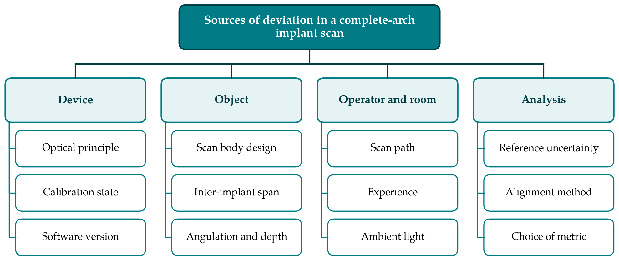
Object factors include the distance between implants, their angulation and depth, and the geometry and material of the scan bodies (Giménez et al., 2014). Precision falls as the distance between scan bodies increases, because errors accumulate as successive images are stitched across featureless tissue (Flügge et al., 2016). Operator and room factors include the scan path (Müller et al., 2016), experience, and ambient lighting, which altered the accuracy of several scanners in a controlled comparison (Revilla-León et al., 2020).
Analysis factors are the least visible and may be the most influential. Many studies superimpose the test scan on the reference by a global best-fit algorithm of the iterative closest point type (Besl and McKay, 1992) and report the mean surface distance. Best-fit alignment distributes error across the arch and can understate a systematic distortion at its ends, a problem analysed for sequential dental scans by O'Toole et al. (2019). Surface distance is also a poor proxy for what the prosthesis experiences, which is the relative position and axis of each implant. Comparative studies that report inter-implant distances and angles are easier to interpret (Vandeweghe et al., 2017).
3. The Proposed Protocol
The protocol consists of six stages. Table 1 lists what each stage specifies and what must be reported. The stages are described below in the order in which they are carried out.
| Stage | Specification | Items to report |
|---|---|---|
| 1. Reference model | Rigid edentulous arch with four to six implant analogues and scan bodies | Material, implant layout, scan body make and batch |
| 2. Reference measurement | Coordinate measuring machine or industrial scanner with traceable calibration | Instrument, stated uncertainty, date |
| 3. Test conditions | Fixed temperature, lighting, calibration and software | Room conditions, versions, calibration record |
| 4. Scanning | Predefined path, trained operators, fixed number of repeats | Path, operators, repeats, discarded scans |
| 5. Registration | Scan body positions extracted by library fitting; alignment on one implant | Software, fitting residuals, alignment rule |
| 6. Metrics and statistics | Linear, angular and three-dimensional deviations; trueness and precision separate | Full distributions, analysis plan |
3.1. Stage 1: Reference model
The model represents an edentulous arch of realistic form with implant analogues placed in a distribution typical of a fixed complete-arch prosthesis, including at least one tilted posterior implant. It is made from a dimensionally stable material, and the analogues are fixed so that they cannot move between sessions. The surface between implants should offer as little texture as an edentulous ridge does, since a richly textured model flatters the stitching algorithm. Scan bodies of a single make and batch are tightened to the manufacturer's torque and left in place for the whole study, because reseating introduces its own error.
3.2. Stage 2: Reference measurement
The reference positions are measured with an instrument at least several times more accurate than the devices under test, such as a tactile coordinate measuring machine or an industrial optical scanner with traceable calibration. The uncertainty of the reference is stated in accordance with the Guide to the Expression of Uncertainty in Measurement (JCGM, 2008). A trueness result smaller than the reference uncertainty has no meaning, and this simple point is often overlooked. The reference measurement is repeated at the end of the study to confirm that the model has not changed.
3.3. Stage 3: Test conditions
Room temperature and lighting are fixed and recorded. Each scanner is calibrated according to its manufacturer's instructions before each session, and hardware and software versions are noted, since updates can change performance. The model is mounted in a phantom head or behind a mask that restricts access to the dimensions of a mouth opening. A model scanned freely on a bench allows scanner movements that are impossible in a patient.
3.4. Stage 4: Scanning
A scan path is defined in advance for each device, following the manufacturer's recommendation where one exists, and is described in enough detail to be repeated. Operators are trained to a stated criterion before data collection. The number of repetitions per scanner and operator is fixed beforehand, and the order of devices is randomised to spread any drift in conditions. Scans that the software rejects or that the operator restarts are counted and reported, since the frequency of failed scans is itself useful information. Files are exported in an open format without smoothing or hole filling.
3.5. Stage 5: Registration
The position and axis of each scan body are obtained by fitting its library geometry to the scanned surface, and the residual of each fit is recorded. Test and reference data sets are then brought into a common coordinate system by aligning on one terminal scan body only, so that deviation accumulates visibly along the arch as it would beneath a rigid framework. Global best-fit superimposition of the whole surface may be reported as a secondary analysis for comparison with earlier work, on the method described for complete-arch scans by Ender and Mehl (2013). It should not be the primary one.
3.6. Stage 6: Metrics and statistics
Three quantities are computed for every implant relative to the reference implant: the deviation in inter-implant distance, the angular deviation of the implant axis, and the three-dimensional displacement of the platform centre. Trueness is the difference between the mean of repeated scans and the reference value. Precision is the dispersion of repeated scans about their own mean, reported both within and between operators. Signed deviations are retained alongside absolute values, since a consistent contraction or expansion of the arch is hidden when only magnitudes are averaged. Deviation data are often skewed, so medians and ranges are given with means, and the analysis plan is fixed before scanning begins.
4. Reporting
A protocol is useful only if studies that follow it can be recognised and checked. Reports should give every item in the right-hand column of Table 1, make the reference coordinates and, where licences permit, the scan files available, and state any departure from the procedure. General guidance on reporting laboratory studies in dentistry applies as well (Krithikadatta et al., 2014). Results should be expressed in the units of the measured quantity and accompanied by the reference uncertainty, without conversion into a single composite score. Rankings of scanners should be avoided unless differences exceed both the reference uncertainty and the between-operator variation.
5. Fitting the Protocol to a Laboratory
The most demanding requirement is the reference measurement, since few dental schools own a coordinate measuring machine. Engineering departments and commercial metrology services provide such measurements with certificates of calibration, and one well-characterised model can be shared between centres. The remaining stages need only equipment that a prosthodontic laboratory already has. Sharing a physical model, or a design file from which identical models are machined, would allow an inter-laboratory comparison of the kind ISO 5725 envisages, and that would be the most direct test of whether the protocol achieves its purpose.
6. Limitations and What Remains to Be Shown
The protocol is proposed and has not been validated. It remains to be shown that laboratories following it obtain concordant results for the same device, and that the single-implant alignment rule gives more informative results than best-fit alignment in practice as well as in principle. The choice of implant layout is one of many possible, and conclusions will not transfer automatically to other numbers, spacings or angulations of implants.
A bench model omits most of what makes complete-arch scanning difficult in a patient: saliva, mobile mucosa, the tongue and cheeks, limited opening and movement. Bench results therefore describe the best a device can do and set an upper bound on clinical expectations. They cannot establish clinical adequacy, which depends on a tolerance for misfit that is itself undefined. Clinical studies using a verified conventional cast or a verification jig as comparator remain necessary, and the metrics proposed here could be carried over to them unchanged.
7. Conclusion
Disagreement about the accuracy of intraoral scanners for complete-arch implant impressions owes much to differences in bench method. The protocol set out here fixes the reference model and its measurement, the test conditions, the scanning procedure, the registration rule and the reported quantities, and it keeps trueness and precision apart as the standards require. Its adoption would not settle which scanner is best. It would allow that question to be asked in a form that different laboratories can answer in the same way.
Conflict of interest
To be declared by the author(s) before publication.
Funding
To be declared by the author(s) before publication.