1. Introduction
Protection settings are a compromise fixed in advance. Pickup currents, time dials and zone reaches are calculated for the range of operating conditions the engineer expects, and they must hold for all of them. The notion that relays might instead adjust themselves to the prevailing state of the system was set out in two companion papers of the late 1980s (Horowitz et al., 1988; Rockefeller et al., 1988), and numerical relays with several setting groups and programmable logic have since made it practicable. Interest has grown with distributed and inverter-based generation, which make both the magnitude and the direction of fault current depend on what happens to be connected (Brahma and Girgis, 2004; Hooshyar and Iravani, 2017).
Meshed networks raise the stakes. In a radial feeder each relay coordinates with one neighbour downstream. In a mesh, directional overcurrent relays form interlocking loops in which every setting constrains several others, a problem classically posed as an optimisation (Urdaneta et al., 1988). An adaptive scheme recomputes or reselects these settings when the topology changes. If it selects wrongly, or if some relays change and others do not, the loss of selectivity is not confined to one location. The scheme therefore needs to be validated as a system, under changing conditions, before it is trusted. This article proposes a procedure for doing so with hardware-in-the-loop simulation. The procedure is described and justified; it is not applied here.
2. Background
Adaptive schemes take several forms. The simplest switches between precalculated setting groups on the status of selected breakers. More elaborate ones hold a table of settings indexed by network configuration, or run a coordination calculation centrally and download the result, as in the microgrid scheme described by Oudalov and Fidigatti (2009). All share three elements that fixed protection lacks: a means of sensing the network state, a rule that maps state to settings, and a mechanism that applies the settings to relays in service. Each is a potential point of failure, and none is exercised by a conventional secondary-injection test.
Real-time digital simulation was developed largely to test protection. The simulator solves the electromagnetic transient equations of the network, by the nodal method of Dommel (1969), with a time step short enough for its outputs to stand in for instrument-transformer secondaries, and it accepts trip signals back from the relay so that the simulated breaker opens when the real relay says so (McLaren et al., 1992; Kuffel et al., 1995). Because the device under test exchanges only signals with the simulator, the arrangement is termed controller hardware-in-the-loop; power hardware-in-the-loop, in which real power flows through an amplifier interface, raises stability questions of its own (Lauss et al., 2016). The present state of the technology is reviewed by Faruque et al. (2015), and its place among other test methods is described in the IEEE guide on protection testing (IEEE, 2009).
3. Test Architecture
Figure 1 shows the closed loop on which the procedure relies. The network model runs on the simulator. Its voltages and currents at each relay location reach the relays either as analogue signals through voltage and current amplifiers or as sampled values on an IEC 61850 process bus. The relays return trip commands and receive breaker status, by hard-wired contacts or by GOOSE messages. The adaptation logic, whether it resides in the relays, in a substation controller or in a central computer, is included as real hardware and software wherever possible, connected through the same communication network it will use in service.
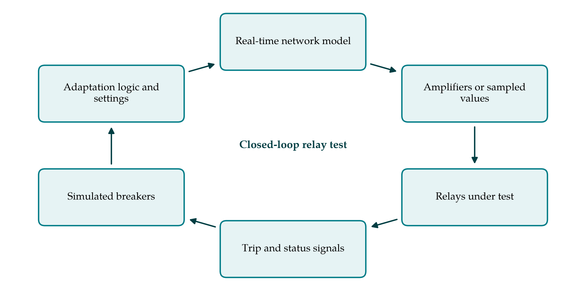
The guiding principle is that everything that decides or communicates should be real, and only the power system should be simulated. A scheme whose adaptation rule has been modelled inside the simulator has had its concept tested but not its implementation. Where the number of relays in the scheme exceeds the number available in the laboratory, the relays bounding the zones under study are real and the remainder are represented by simulator models, with the substitution recorded as a limitation.
4. The Proposed Procedure
The procedure runs through six phases, taken in order. Table 1 lists the classes of test that make up its core and the criterion applied to each.
| Test class | What is varied | Pass criterion |
|---|---|---|
| Static selectivity | Fault location, type and resistance in each fixed topology | Correct relays trip; margins to backup maintained |
| Security | External faults, load pickup, transformer energisation, power swings | No relay of the scheme operates |
| Setting transition | Topology change followed by a fault at varied delays | Selective tripping before, during and after the change |
| Partial update | One or more relays prevented from receiving new settings | Scheme detects the mismatch and enters the defined fallback |
| Communication impairment | Loss, delay or corruption of status and setting messages | Fallback within the stated time; no unwanted trip |
| Instrument-transformer stress | Current-transformer saturation and DC offset | Operate times remain within the stated tolerance |
| Evolving and simultaneous faults | Second fault or fault-type change during clearing | Both faults cleared without loss of the unfaulted mesh |
4.1. Acceptance criteria
Before any equipment is connected, the criteria for a pass are written down. For each protected element they state which relays should operate for an internal fault and in what time, which should restrain, and what coordination margin must separate primary from backup operation. Functional standards for the protection elements concerned, such as IEC 60255-121 for distance protection (IEC, 2014), supply the vocabulary for operate time and reach accuracy. Criteria specific to adaptation are added: the maximum time from a topology change to the new settings being active in all relays, the required behaviour for a fault that occurs during that interval, and the fallback state on loss of communication.
4.2. Model construction and verification
The network model must be detailed where the relays measure and may be reduced elsewhere. Lines within the protected mesh are modelled with distributed parameters or adequate pi-sections, current transformers with their saturation characteristics, and sources with the sequence impedances that govern fault current. Inverter-based sources require particular care, since their fault contribution is set by control and current limits and not by an impedance (Hooshyar and Iravani, 2017). The model is verified against an independent short-circuit calculation for each topology, and the comparison is kept. A scheme tested on a wrong model has not been tested.
4.3. Interface characterisation
Delays in the loop are measured before they can be mistaken for relay behaviour. With analogue injection these are the conversion and amplifier delays and the input and output scan of the simulator. With a process bus they are the publication and network delays of sampled values and GOOSE messages, for which IEC 61850-5 defines transfer-time classes by application (IEC, 2013). The characterisation consists of applying a step at the simulator, recording its arrival at the relay terminals and the return of a directly looped signal, and repeating the measurement enough times to see the spread. The resulting figure is subtracted from, or reported alongside, every operate time.
4.4. Scenario matrix
The scenarios are the heart of the validation, and they are too many to enumerate by hand. The factors are network topology, generation dispatch, fault location, fault type, fault resistance, point on wave and, for the adaptive scheme, the timing of events relative to a setting change. A full factorial crossing of these is neither feasible nor necessary. The methods of experimental design (Montgomery, 2017) allow a fractional set to be chosen that still exposes main effects and two-factor interactions, supplemented by cases that engineering judgement marks as critical: faults at zone boundaries, weak-infeed conditions and the topologies with the smallest coordination margins.
The transition and partial-update classes distinguish this procedure from the testing of fixed protection. In a transition test the simulator opens or closes a breaker to change the topology and then applies a fault after a delay that is swept from zero to beyond the specified adaptation time, so that the fault falls before, during and after the settings change. In a partial-update test the communication path to one relay is interrupted so that it retains its old group while its neighbours adopt the new one. These are the conditions under which relay loops in a mesh can lose coordination.
4.5. Automated execution
The scenarios are executed by script. Each run sets the topology and dispatch, waits for steady state, confirms the active setting group of every relay, applies the event sequence and records simulator waveforms, relay event logs and the communication traffic. Recordings are stored in the COMTRADE format (IEEE, 2013) so that any case can later be replayed to a single relay on a conventional test set. Runs are repeated with different points on wave, since operate time varies with fault inception angle, and the random seed and software versions are logged for reproducibility.
4.6. Evaluation and reporting
Each run is scored automatically against the criteria: which relays operated, in what order and time, and whether the breakers that opened were the correct ones. Failures are classified by cause as setting error, adaptation-logic error, communication fault, relay algorithm behaviour or test artefact. The last class is important; an unexpected trip caused by an amplifier limit or a modelling shortcut must be recognised as such and the test corrected. The report states the scenarios run, the coverage achieved for each factor, the failures with their classification and disposition, and the conditions that were not tested.
5. Fitting the Procedure to Practice
The effort required is dominated by the model and the scripting, not by the runs themselves, which take seconds each. A utility without its own simulator can specify the procedure for a manufacturer or a university laboratory and witness the critical cases. Protection textbooks stress that dependability and security pull in opposite directions (Horowitz and Phadke, 2014), and the scenario matrix should be balanced accordingly, with as much attention to cases where nothing should trip as to faults. Firmware versions of the relays and the controller are part of the test record, because the validation applies to those versions and must be at least partly repeated when they change.
6. Limitations and What Remains to Be Shown
The procedure is a proposal and has not been validated in this article. Its value would have to be demonstrated by applying it to an adaptive scheme and showing that it reveals defects which conventional testing missed, at a cost that a project can bear. Three limitations are inherent. A hardware-in-the-loop test is only as good as the network model, and models of inverter fault behaviour in particular depend on manufacturer data. Controller-level testing omits the primary equipment, so breaker failure, instrument-transformer wiring errors and electromagnetic interference in the substation are outside its reach and remain matters for commissioning. And no finite scenario set proves correctness; the fractional design gives structured coverage, not a guarantee. How large a matrix is sufficient for a mesh of given size is an open question on which reported experience would be valuable.
7. Conclusion
Adaptive protection in a meshed network should be validated as a closed-loop system, with the real relays, the real adaptation logic and the real communication path connected to a simulated network that changes while they act. The procedure proposed here organises that validation into written acceptance criteria, a verified model, a characterised interface, a designed scenario matrix that includes setting transitions and communication failures, scripted execution and classified results. It remains to be tried on working schemes, and the test classes in Table 1 are offered as a starting point to be revised in the light of such trials.
Conflict of interest
To be declared by the author(s) before publication.
Funding
To be declared by the author(s) before publication.